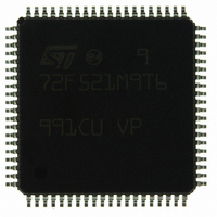
ST72F521M9T6 STMicroelectronics, ST72F521M9T6 Datasheet - Page 108

ST72F521M9T6
Manufacturer Part Number
ST72F521M9T6
Description
IC MCU 8BIT 60K FLASH 80-TQFP
Manufacturer
STMicroelectronics
Series
ST7r
Datasheet
1.ST72F521M9T6.pdf
(215 pages)
Specifications of ST72F521M9T6
Core Processor
ST7
Core Size
8-Bit
Speed
8MHz
Connectivity
CAN, LINSCI, SPI
Peripherals
LVD, POR, PWM, WDT
Number Of I /o
64
Program Memory Size
60KB (60K x 8)
Program Memory Type
FLASH
Ram Size
2K x 8
Voltage - Supply (vcc/vdd)
3.8 V ~ 5.5 V
Data Converters
A/D 16x10b
Oscillator Type
Internal
Operating Temperature
-40°C ~ 85°C
Package / Case
80-TQFP, 80-VQFP
Processor Series
ST72F5x
Core
ST7
Data Bus Width
8 bit
Data Ram Size
2048 B
Interface Type
CAN, I2C, SCI, SPI
Maximum Clock Frequency
8 MHz
Number Of Programmable I/os
64
Number Of Timers
5
Operating Supply Voltage
3.8 V to 5.5 V
Maximum Operating Temperature
+ 85 C
Mounting Style
SMD/SMT
Minimum Operating Temperature
- 40 C
On-chip Adc
10 bit
For Use With
497-6453 - BOARD EVAL BASED ON ST7LNBX497-5046 - KIT TOOL FOR ST7/UPSD/STR7 MCU
Lead Free Status / RoHS Status
Lead free / RoHS Compliant
Eeprom Size
-
Lead Free Status / Rohs Status
Details
Other names
497-8244
ST72F521M9T6
ST72F521M9T6
Available stocks
Company
Part Number
Manufacturer
Quantity
Price
Company:
Part Number:
ST72F521M9T6
Manufacturer:
ST
Quantity:
37 800
Company:
Part Number:
ST72F521M9T6
Manufacturer:
STMicroelectronics
Quantity:
10 000
Company:
Part Number:
ST72F521M9T6TR
Manufacturer:
STMicroelectronics
Quantity:
10 000
ST72F521, ST72521B
SERIAL COMMUNICATIONS INTERFACE (Cont’d)
10.6.4.9 Clock Deviation Causes
The causes which contribute to the total deviation
are:
All the deviations of the system should be added
and compared to the SCI clock tolerance:
D
Figure 63. Bit Sampling in Reception Mode
RDI LINE
108/215
Sample
TRA
clock
– D
– D
– D
– D
oscillator error of the transmitter or the trans-
mitter is transmitting at a different baud rate).
tion of the receiver.
receiver: This deviation can occur during the
reception of one complete SCI message as-
suming that the deviation has been compen-
sated at the beginning of the message.
(generally due to the transceivers)
+ D
TRA
QUANT
REC
TCL
: Deviation due to the transmission line
QUANT
: Deviation due to transmitter error (Local
: Deviation of the local oscillator of the
: Error due to the baud rate quantisa-
+ D
1
REC
2
+ D
3
TCL
< 3.75%
4
7/16
5
6
One bit time
7
sampled values
8
10.6.4.10 Noise Error Causes
See also description of Noise error in
10.6.4.3.
Start bit
The noise flag (NF) is set during start bit reception
if one of the following conditions occurs:
1. A valid falling edge is not detected. A falling
2. During sampling of the 16 samples, if one of the
Therefore, a valid Start Bit must satisfy both the
above conditions to prevent the Noise Flag getting
set.
Data Bits
The noise flag (NF) is set during normal data bit re-
ception if the following condition occurs:
– During the sampling of 16 samples, if all three
Therefore, a valid Data Bit must have samples 8, 9
and 10 at the same value to prevent the Noise
Flag getting set.
samples numbered 8, 9 and10 are not the same.
The majority of the 8th, 9th and 10th samples is
considered as the bit value.
edge is considered to be valid if the 3 consecu-
tive samples before the falling edge occurs are
detected as '1' and, after the falling edge
occurs, during the sampling of the 16 samples,
if one of the samples numbered 3, 5 or 7 is
detected as a “1”.
samples numbered 8, 9 or 10 is detected as a
“1”.
9
10
11
12
13
6/16
7/16
14
15
16
Section


