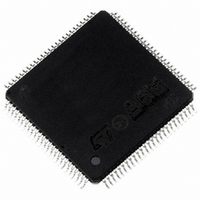
ST92F150CV1TB STMicroelectronics, ST92F150CV1TB Datasheet - Page 149

ST92F150CV1TB
Manufacturer Part Number
ST92F150CV1TB
Description
MCU 8BIT 128K FLASH 100TQFP
Manufacturer
STMicroelectronics
Series
ST9r
Datasheet
1.ST92F150CV1TB.pdf
(429 pages)
Specifications of ST92F150CV1TB
Core Processor
ST9
Core Size
8/16-Bit
Speed
24MHz
Connectivity
CAN, EBI/EMI, I²C, LIN, SCI, SPI
Peripherals
DMA, LVD, POR, PWM, WDT
Number Of I /o
77
Program Memory Size
128KB (128K x 8)
Program Memory Type
FLASH
Eeprom Size
1K x 8
Ram Size
4K x 8
Voltage - Supply (vcc/vdd)
4.5 V ~ 5.5 V
Data Converters
A/D 16x10b
Oscillator Type
Internal
Operating Temperature
-40°C ~ 105°C
Package / Case
100-TQFP, 100-VQFP
Processor Series
ST92F15x
Core
ST9
Data Bus Width
8 bit, 16 bit
Data Ram Size
6 KB
Interface Type
CAN, I2C, SCI, SPI
Maximum Clock Frequency
24 MHz
Number Of Programmable I/os
80
Number Of Timers
5 x 16 bit
Operating Supply Voltage
4.5 V to 5.5 V
Maximum Operating Temperature
+ 105 C
Mounting Style
SMD/SMT
Development Tools By Supplier
ST92F150-EPB
Minimum Operating Temperature
- 40 C
On-chip Adc
16 bit x 10 bit
Lead Free Status / RoHS Status
Lead free / RoHS Compliant
Other names
497-4883
Available stocks
Company
Part Number
Manufacturer
Quantity
Price
Company:
Part Number:
ST92F150CV1TB
Manufacturer:
STMicroelectronics
Quantity:
10 000
- Current page: 149 of 429
- Download datasheet (8Mb)
EXTERNAL MEMORY INTERFACE REGISTERS (Cont’d)
EXTERNAL MEMORY REGISTER 2 (EMR2)
R246 - Read/Write
Register Page: 21
Reset value: 0001 1111 (1Fh)
Bit 7 = Reserved.
Bit 6 = ENCSR: Enable Code Segment Register.
This bit affects the ST9 CPU behavior whenever
an interrupt request is issued.
0: The CPU works in original ST9 compatibility
1: If ENCSR is set, ISR is only used to point to the
7
-
mode concerning stack frame during interrupts.
For the duration of the interrupt service routine,
ISR is used instead of CSR, and the interrupt
stack frame is identical to that of the original
ST9: only the PC and Flags are pushed. This
avoids saving the CSR on the stack in the event
of an interrupt, thus ensuring a faster interrupt
response time. The drawback is that it is not
possible for an interrupt service routine to per-
form inter-segment calls or jumps: these instruc-
tions would update the CSR, which, in this case,
is not used (ISR is used instead). The code seg-
ment size for all interrupt service routines is thus
limited to 64K bytes.
interrupt vector table and to initialize the CSR at
the beginning of the interrupt service routine: the
old CSR is pushed onto the stack together with
the PC and flags, and CSR is then loaded with
ENCSR DPRREM MEMSEL LAS1 LAS0 UAS1 UAS0
ST92F124/F150/F250 - EXTERNAL MEMORY INTERFACE (EXTMI)
0
Bit 5 = DPRREM: Data Page Registers remapping
0: The locations of the four MMU (Memory Man-
1: The four MMU Data Page Registers are
Refer to
Bit 4 = MEMSEL: Memory Selection.
Warning: Must be kept at 1.
Bit 3:2 = LAS[1:0]: Lower memory address strobe
stretch.
These two bits contain the number of wait cycles
(from 0 to 3) to add to the System Clock to stretch
AS during external lower memory block accesses
(A21=”0”). The reset value is 3.
the contents of ISR. In this case, iret will also re-
store CSR from the stack. This approach allows
interrupt service routines to access the entire
4Mbytes of address space; the drawback is that
the interrupt response time is slightly increased,
because of the need to also save CSR on the
stack. Full compatibility with the original ST9 is
lost in this case, because the interrupt stack
frame is different; this difference, however,
should not affect the vast majority of programs.
agement Unit) Data Page Registers (DPR0,
DPR1, DPR2 and DPR3) are in page 21.
swapped with that of the Data Registers of ports
0-3.
Figure 73
149/429
9
Related parts for ST92F150CV1TB
Image
Part Number
Description
Manufacturer
Datasheet
Request
R

Part Number:
Description:
BOARD PROGRAM FOR ST92F150 MCU
Manufacturer:
STMicroelectronics
Datasheet:

Part Number:
Description:
BOARD EVALUATION FOR ST9 SERIES
Manufacturer:
STMicroelectronics
Datasheet:

Part Number:
Description:
BOARD EMULATOR FOR ST9 SERIES
Manufacturer:
STMicroelectronics
Datasheet:

Part Number:
Description:
MCU, MPU & DSP Development Tools ST9 Dedication Board
Manufacturer:
STMicroelectronics
Datasheet:

Part Number:
Description:
STMicroelectronics [RIPPLE-CARRY BINARY COUNTER/DIVIDERS]
Manufacturer:
STMicroelectronics
Datasheet:

Part Number:
Description:
STMicroelectronics [LIQUID-CRYSTAL DISPLAY DRIVERS]
Manufacturer:
STMicroelectronics
Datasheet:

Part Number:
Description:
BOARD EVAL FOR MEMS SENSORS
Manufacturer:
STMicroelectronics
Datasheet:

Part Number:
Description:
NPN TRANSISTOR POWER MODULE
Manufacturer:
STMicroelectronics
Datasheet:

Part Number:
Description:
TURBOSWITCH ULTRA-FAST HIGH VOLTAGE DIODE
Manufacturer:
STMicroelectronics
Datasheet:

Part Number:
Description:
Manufacturer:
STMicroelectronics
Datasheet:

Part Number:
Description:
DIODE / SCR MODULE
Manufacturer:
STMicroelectronics
Datasheet:

Part Number:
Description:
DIODE / SCR MODULE
Manufacturer:
STMicroelectronics
Datasheet:


