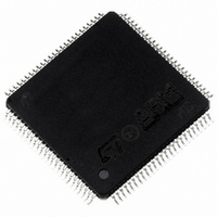
ST92F150CV1TB STMicroelectronics, ST92F150CV1TB Datasheet - Page 370

ST92F150CV1TB
Manufacturer Part Number
ST92F150CV1TB
Description
MCU 8BIT 128K FLASH 100TQFP
Manufacturer
STMicroelectronics
Series
ST9r
Datasheet
1.ST92F150CV1TB.pdf
(429 pages)
Specifications of ST92F150CV1TB
Core Processor
ST9
Core Size
8/16-Bit
Speed
24MHz
Connectivity
CAN, EBI/EMI, I²C, LIN, SCI, SPI
Peripherals
DMA, LVD, POR, PWM, WDT
Number Of I /o
77
Program Memory Size
128KB (128K x 8)
Program Memory Type
FLASH
Eeprom Size
1K x 8
Ram Size
4K x 8
Voltage - Supply (vcc/vdd)
4.5 V ~ 5.5 V
Data Converters
A/D 16x10b
Oscillator Type
Internal
Operating Temperature
-40°C ~ 105°C
Package / Case
100-TQFP, 100-VQFP
Processor Series
ST92F15x
Core
ST9
Data Bus Width
8 bit, 16 bit
Data Ram Size
6 KB
Interface Type
CAN, I2C, SCI, SPI
Maximum Clock Frequency
24 MHz
Number Of Programmable I/os
80
Number Of Timers
5 x 16 bit
Operating Supply Voltage
4.5 V to 5.5 V
Maximum Operating Temperature
+ 105 C
Mounting Style
SMD/SMT
Development Tools By Supplier
ST92F150-EPB
Minimum Operating Temperature
- 40 C
On-chip Adc
16 bit x 10 bit
Lead Free Status / RoHS Status
Lead free / RoHS Compliant
Other names
497-4883
Available stocks
Company
Part Number
Manufacturer
Quantity
Price
Company:
Part Number:
ST92F150CV1TB
Manufacturer:
STMicroelectronics
Quantity:
10 000
- Current page: 370 of 429
- Download datasheet (8Mb)
10-BIT ANALOG TO DIGITAL CONVERTER (ADC)
REGISTER DESCRIPTION (Cont’d)
COMPARE RESULT REGISTER (CRR)
R243 - Read/Write
Register Page: 63
Reset Value: 0000 xxxx (0xh)
Two adjacent channels (identified as A and B) can
be selected through CLR1 register programming
(bits CC[3:0]); a level window for the converted an-
alog input can be defined on these channels.
Bits 7 = CBU: Compare Register Ch. B Upper
Threshold
Set when converted data on channel B is greater
than the threshold value set in UTBHR/UTBLR
registers.
Bits 6 = CAU: Compare Register Ch. A Upper
Threshold
Set when converted data on channel A is greater
than the threshold value set in UTAHR/UTALR
registers.
Bits 5 = CBL: Compare Register Ch. B Lower
Threshold
Set when converted data on channel B is less than
the threshold value set in LTBHR/LTBLR regis-
ters.
Bits 4 = CAL: Compare Register Ch. A Lower
Threshold
Set when converted data on channel A is less than
the threshold value set in LTAHR/LTALR regis-
ters.
Bits 3:0 = Don’t care
LOWER THRESHOLD REGISTERS (LTiHR/
LTiLR)
The two pairs of Lower Threshold High/Low regis-
ters are used to store the user programmable low-
er threshold 10-bit values, to be compared with the
current conversion results, thus setting the lower
window limit.
370/429
9
CBU
7
CAU
CBL
CAL
x
x
x
0
x
CHANNEL A LOWER THRESHOLD HIGH
REGISTER (LTAHR)
R244 - Read
Register Page: 63
Reset Value: undefined
Bits 7:0 = LTA.[9:2]: Channel A [9:2] bit Lower
Threshold
CHANNEL A LOWER THRESHOLD LOW
REGISTER (LTALR)
R245 - Read/Write
Register Page: 63
Reset Value: xx00 0000
Bits 7:6 = LTA.[1:0]: Channel A [1:0] bit Lower
Threshold
Bits 5:0 = Reserved, forced by hardware to 0.
CHANNEL B LOWER THRESHOLD HIGH REG-
ISTER (LTBHR)
R246 - Read/Write
Register Page: 63
Reset Value: undefined
Bits 7:0 = LTB.[9:2]: Channel B [9:2] bit Lower
Threshold
LTA.9 LTA.8 LTA.7 LTA.6 LTA.5 LTA.4 LTA.3 LTA.2
LTA.1 LTA.0
LTB.7 LTB.7 LTB.5 LTB.4 LTB.3 LTB.2 LTB.1 LTB.0
7
7
7
0
0
0
0
0
0
0
0
0
Related parts for ST92F150CV1TB
Image
Part Number
Description
Manufacturer
Datasheet
Request
R

Part Number:
Description:
BOARD PROGRAM FOR ST92F150 MCU
Manufacturer:
STMicroelectronics
Datasheet:

Part Number:
Description:
BOARD EVALUATION FOR ST9 SERIES
Manufacturer:
STMicroelectronics
Datasheet:

Part Number:
Description:
BOARD EMULATOR FOR ST9 SERIES
Manufacturer:
STMicroelectronics
Datasheet:

Part Number:
Description:
MCU, MPU & DSP Development Tools ST9 Dedication Board
Manufacturer:
STMicroelectronics
Datasheet:

Part Number:
Description:
STMicroelectronics [RIPPLE-CARRY BINARY COUNTER/DIVIDERS]
Manufacturer:
STMicroelectronics
Datasheet:

Part Number:
Description:
STMicroelectronics [LIQUID-CRYSTAL DISPLAY DRIVERS]
Manufacturer:
STMicroelectronics
Datasheet:

Part Number:
Description:
BOARD EVAL FOR MEMS SENSORS
Manufacturer:
STMicroelectronics
Datasheet:

Part Number:
Description:
NPN TRANSISTOR POWER MODULE
Manufacturer:
STMicroelectronics
Datasheet:

Part Number:
Description:
TURBOSWITCH ULTRA-FAST HIGH VOLTAGE DIODE
Manufacturer:
STMicroelectronics
Datasheet:

Part Number:
Description:
Manufacturer:
STMicroelectronics
Datasheet:

Part Number:
Description:
DIODE / SCR MODULE
Manufacturer:
STMicroelectronics
Datasheet:

Part Number:
Description:
DIODE / SCR MODULE
Manufacturer:
STMicroelectronics
Datasheet:


