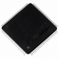
ST92F150CV1TB STMicroelectronics, ST92F150CV1TB Datasheet - Page 342

ST92F150CV1TB
Manufacturer Part Number
ST92F150CV1TB
Description
MCU 8BIT 128K FLASH 100TQFP
Manufacturer
STMicroelectronics
Series
ST9r
Datasheet
1.ST92F150CV1TB.pdf
(429 pages)
Specifications of ST92F150CV1TB
Core Processor
ST9
Core Size
8/16-Bit
Speed
24MHz
Connectivity
CAN, EBI/EMI, I²C, LIN, SCI, SPI
Peripherals
DMA, LVD, POR, PWM, WDT
Number Of I /o
77
Program Memory Size
128KB (128K x 8)
Program Memory Type
FLASH
Eeprom Size
1K x 8
Ram Size
4K x 8
Voltage - Supply (vcc/vdd)
4.5 V ~ 5.5 V
Data Converters
A/D 16x10b
Oscillator Type
Internal
Operating Temperature
-40°C ~ 105°C
Package / Case
100-TQFP, 100-VQFP
Processor Series
ST92F15x
Core
ST9
Data Bus Width
8 bit, 16 bit
Data Ram Size
6 KB
Interface Type
CAN, I2C, SCI, SPI
Maximum Clock Frequency
24 MHz
Number Of Programmable I/os
80
Number Of Timers
5 x 16 bit
Operating Supply Voltage
4.5 V to 5.5 V
Maximum Operating Temperature
+ 105 C
Mounting Style
SMD/SMT
Development Tools By Supplier
ST92F150-EPB
Minimum Operating Temperature
- 40 C
On-chip Adc
16 bit x 10 bit
Lead Free Status / RoHS Status
Lead free / RoHS Compliant
Other names
497-4883
Available stocks
Company
Part Number
Manufacturer
Quantity
Price
Company:
Part Number:
ST92F150CV1TB
Manufacturer:
STMicroelectronics
Quantity:
10 000
- Current page: 342 of 429
- Download datasheet (8Mb)
CONTROLLER AREA NETWORK (bxCAN)
CONTROLLER AREA NETWORK (Cont’d)
– The transmit interrupt can be generated by the
– The FIFO 0 interrupt can be generated by the
– The FIFO 1 interrupt can be generated by the
342/429
9
following events:
following events:
following events:
– Transmit mailbox 0 becomes empty, RQCP0
– Transmit mailbox 1 becomes empty, RQCP1
– Transmit mailbox 2 becomes empty, RQCP2
– Reception of a new message, FMP bits in the
– FIFO0 full condition, FULL bit in the CRFR0
– FIFO0 overrun condition, FOVR bit in the
– Reception of a new message, FMP bits in the
– FIFO1 full condition, FULL bit in the CRFR1
– FIFO1 overrun condition, FOVR bit in the
bit in the CTSR register set.
bit in the CTSR register set.
bit in the CTSR register set.
CRFR0 register incremented.
register set.
CRFR0 register set.
CRFR1 register incremented.
register set.
CRFR1 register set.
– The error and status change interrupt can be
10.10.7 Register Access Protection
Erroneous access to certain configuration regis-
ters can cause the hardware to temporarily disturb
the whole CAN network. Therefore the following
registers can be modified by software only while
the hardware is in initialization mode:
CBTR0, CBTR1, CFCR0, CFCR1, CFMR and
CDGR registers.
Although the transmission of incorrect data will not
cause problems at the CAN network level, it can
severely disturb the application. A transmit mail-
box can be only modified by software while it is in
empty state, refer to
States
The filters must be deactivated before their value
can be modified by software. The modification of
the filter configuration (scale or mode) can be
done by software only in initialization mode.
generated by the following events:
– Error condition, for more details on error con-
– Wake-up condition, SOF monitored on the
ditions please refer to the CAN Error Status
register (CESR).
CAN Rx signal.
Figure 147.Transmit Mailbox
Related parts for ST92F150CV1TB
Image
Part Number
Description
Manufacturer
Datasheet
Request
R

Part Number:
Description:
BOARD PROGRAM FOR ST92F150 MCU
Manufacturer:
STMicroelectronics
Datasheet:

Part Number:
Description:
BOARD EVALUATION FOR ST9 SERIES
Manufacturer:
STMicroelectronics
Datasheet:

Part Number:
Description:
BOARD EMULATOR FOR ST9 SERIES
Manufacturer:
STMicroelectronics
Datasheet:

Part Number:
Description:
MCU, MPU & DSP Development Tools ST9 Dedication Board
Manufacturer:
STMicroelectronics
Datasheet:

Part Number:
Description:
STMicroelectronics [RIPPLE-CARRY BINARY COUNTER/DIVIDERS]
Manufacturer:
STMicroelectronics
Datasheet:

Part Number:
Description:
STMicroelectronics [LIQUID-CRYSTAL DISPLAY DRIVERS]
Manufacturer:
STMicroelectronics
Datasheet:

Part Number:
Description:
BOARD EVAL FOR MEMS SENSORS
Manufacturer:
STMicroelectronics
Datasheet:

Part Number:
Description:
NPN TRANSISTOR POWER MODULE
Manufacturer:
STMicroelectronics
Datasheet:

Part Number:
Description:
TURBOSWITCH ULTRA-FAST HIGH VOLTAGE DIODE
Manufacturer:
STMicroelectronics
Datasheet:

Part Number:
Description:
Manufacturer:
STMicroelectronics
Datasheet:

Part Number:
Description:
DIODE / SCR MODULE
Manufacturer:
STMicroelectronics
Datasheet:

Part Number:
Description:
DIODE / SCR MODULE
Manufacturer:
STMicroelectronics
Datasheet:


