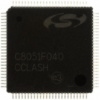
C8051F040-GQ Silicon Laboratories Inc, C8051F040-GQ Datasheet - Page 271

C8051F040-GQ
Manufacturer Part Number
C8051F040-GQ
Description
IC 8051 MCU 64K FLASH 100TQFP
Manufacturer
Silicon Laboratories Inc
Series
C8051F04xr
Datasheets
1.C8051F040-TB.pdf
(328 pages)
2.C8051F040-TB.pdf
(2 pages)
3.C8051F043-GQ.pdf
(328 pages)
Specifications of C8051F040-GQ
Program Memory Type
FLASH
Program Memory Size
64KB (64K x 8)
Package / Case
100-TQFP, 100-VQFP
Core Processor
8051
Core Size
8-Bit
Speed
25MHz
Connectivity
CAN, EBI/EMI, SMBus (2-Wire/I²C), SPI, UART/USART
Peripherals
Brown-out Detect/Reset, POR, PWM, Temp Sensor, WDT
Number Of I /o
64
Ram Size
4.25K x 8
Voltage - Supply (vcc/vdd)
2.7 V ~ 3.6 V
Data Converters
A/D 8x8b, 13x12b; D/A 2x10b, 2x12b
Oscillator Type
Internal
Operating Temperature
-40°C ~ 85°C
Processor Series
C8051F0x
Core
8051
Data Bus Width
8 bit
Data Ram Size
4.25 KB
Interface Type
CAN/SMBus/SPI/UART
Maximum Clock Frequency
25 MHz
Number Of Programmable I/os
64
Number Of Timers
5
Operating Supply Voltage
2.7 V to 3.6 V
Maximum Operating Temperature
+ 85 C
Mounting Style
SMD/SMT
3rd Party Development Tools
PK51, CA51, A51, ULINK2
Development Tools By Supplier
C8051F040DK
Minimum Operating Temperature
- 40 C
On-chip Adc
8-ch x 8-bit or 13-ch x 12-bit
On-chip Dac
2-ch x 12-bit
No. Of I/o's
64
Ram Memory Size
4352Byte
Cpu Speed
25MHz
No. Of Timers
5
Rohs Compliant
Yes
Data Rom Size
64 KB
A/d Bit Size
12 bit
A/d Channels Available
13
Height
1 mm
Length
14 mm
Supply Voltage (max)
3.6 V
Supply Voltage (min)
2.7 V
Width
14 mm
Package
100TQFP
Device Core
8051
Family Name
C8051F04x
Maximum Speed
25 MHz
Lead Free Status / RoHS Status
Lead free / RoHS Compliant
For Use With
336-1205 - DEV KIT FOR F040/F041/F042/F043
Eeprom Size
-
Lead Free Status / Rohs Status
Lead free / RoHS Compliant
Other names
336-1204
Available stocks
Company
Part Number
Manufacturer
Quantity
Price
Company:
Part Number:
C8051F040-GQ
Manufacturer:
SiliconL
Quantity:
702
Company:
Part Number:
C8051F040-GQ
Manufacturer:
Silicon Laboratories Inc
Quantity:
10 000
Company:
Part Number:
C8051F040-GQR
Manufacturer:
Silicon Laboratories Inc
Quantity:
10 000
Part Number:
C8051F040-GQR
Manufacturer:
SILICON LABS/èٹ¯ç§‘
Quantity:
20 000
Broadcast Address = 00111111
21.3. Configuration of a Masked Address
The UART0 address is configured via two SFRs: SADDR0 (Serial Address) and SADEN0 (Serial Address
Enable). SADEN0 sets the bit mask for the address held in SADDR0: bits set to logic 1 in SADEN0 corre-
spond to bits in SADDR0 that are checked against the received address byte; bits set to logic 0 in SADEN0
correspond to “don’t care” bits in SADDR0.
Setting the SM20 bit (SCON0.5) configures UART0 such that when a stop bit is received, UART0 will gen-
erate an interrupt only if the ninth bit is logic 1 (RB80 = ‘1’) and the received data byte matches the UART0
slave address. Following the received address interrupt, the slave will clear its SM20 bit to enable inter-
rupts on the reception of the following data byte(s). Once the entire message is received, the addressed
slave resets its SM20 bit to ignore all transmissions until it receives the next address byte. While SM20 is
logic 1, UART0 ignores all bytes that do not match the UART0 address and include a ninth bit that is logic
1.
21.4. Broadcast Addressing
Multiple addresses can be assigned to a single slave and/or a single address can be assigned to multiple
slaves, thereby enabling "broadcast" transmissions to more than one slave simultaneously. The broadcast
address is the logical OR of registers SADDR0 and SADEN0, and ‘0’s of the result are treated as “don’t
cares”. Typically a broadcast address of 0xFF (hexadecimal) is acknowledged by all slaves, assuming
“don’t care” bits as ‘1’s. The master processor can be configured to receive all transmissions or a protocol
can be implemented such that the master/slave role is temporarily reversed to enable half-duplex trans-
mission between the original master and slave(s).
Note in the above examples 4, 5, and 6, each slave would recognize as “valid” an address of 0xFF as a
broadcast address. Also note that examples 4, 5, and 6 uses the same SADDR0 and SADEN0 register
values as shown in the examples 1, 2, and 3 respectively (slaves #1, 2, and 3). Thus, a master could
address each slave device individually using a masked address, and also broadcast to all three slave
devices. For example, if a Master were to send an address “11110101”, only slave #1 would recognize the
address as valid. If a master were to then send an address of “11111111”, all three slave devices would rec-
ognize the address as a valid broadcast address.
UART0 Address = xxxx0101
Example 1, SLAVE #1
SADDR0
SADEN0
Example 4, SLAVE #1
SADDR0
SADEN0
= 00110101
= 00001111
= 00110101
= 00001111
Where all ZEROES in the Broadcast address are don’t cares.
Broadcast Address = 11110111
UART0 Address = 0011xx01
Example 2, SLAVE #2
SADDR0
SADEN0
SADDR0
SADEN0
Example 5, SLAVE #2
Rev. 1.5
C8051F040/1/2/3/4/5/6/7
00110101
11110011
= 00110101
= 11110011
=
=
Broadcast Address = 11110101
UART0 Address = 00xxxxxx
Example 3, SLAVE #3
SADDR0
SADEN0
Example 6, SLAVE #3
SADDR0
SADEN0
= 00110101
= 11000000
= 00110101
= 11000000
271


