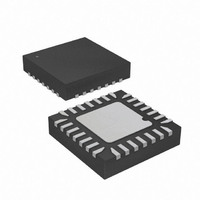
ATTINY48-MMU Atmel, ATTINY48-MMU Datasheet - Page 22

ATTINY48-MMU
Manufacturer Part Number
ATTINY48-MMU
Description
MCU AVR 5K FLASH 12MHZ 28-QFN
Manufacturer
Atmel
Series
AVR® ATtinyr
Specifications of ATTINY48-MMU
Core Processor
AVR
Core Size
8-Bit
Speed
12MHz
Connectivity
I²C, SPI
Peripherals
Brown-out Detect/Reset, POR, WDT
Number Of I /o
24
Program Memory Size
4KB (2K x 16)
Program Memory Type
FLASH
Eeprom Size
64 x 8
Ram Size
256 x 8
Voltage - Supply (vcc/vdd)
1.8 V ~ 5.5 V
Data Converters
A/D 6x10b
Oscillator Type
Internal
Operating Temperature
-40°C ~ 85°C
Package / Case
28-VQFN Exposed Pad, 28-HVQFN, 28-SQFN, 28-DHVQFN
Processor Series
ATTINY4x
Core
AVR8
Data Bus Width
8 bit
Data Ram Size
256 B
Interface Type
2-Wire, I2S, SPI
Maximum Clock Frequency
12 MHz
Number Of Programmable I/os
24
Number Of Timers
2
Maximum Operating Temperature
+ 85 C
Mounting Style
SMD/SMT
3rd Party Development Tools
EWAVR, EWAVR-BL
Development Tools By Supplier
ATAVRDRAGON, ATSTK500, ATSTK600, ATAVRISP2, ATAVRONEKIT
Minimum Operating Temperature
- 40 C
On-chip Adc
10 bit, 6 Channel
Package
28VQFN EP
Device Core
AVR
Family Name
ATtiny
Maximum Speed
12 MHz
Operating Supply Voltage
2.5|3.3|5 V
For Use With
ATAVRDRAGON - KIT DRAGON 32KB FLASH MEM AVR
Lead Free Status / RoHS Status
Lead free / RoHS Compliant
- Current page: 22 of 302
- Download datasheet (9Mb)
5.3.5
22
ATtiny48/88
Preventing EEPROM Corruption
To write an EEPROM memory location follow the procedure below:
The EEPE bit remains set until the write operation has completed. While the device is busy with
programming, it is not possible to do any other EEPROM operations.
During periods of low V
too low for the CPU and the EEPROM to operate properly. These issues are the same as for
board level systems using EEPROM, and the same design solutions should be applied.
At low supply voltages data in EEPROM can be corrupted in two ways:
EEPROM data corruption is avoided by keeping the device in reset during periods of insufficient
power supply voltage. This is easily done by enabling the internal Brown-Out Detector (BOD). If
BOD detection levels are not sufficient for the design, an external reset circuit for low V
used.
Provided that supply voltage is sufficient, an EEPROM write operation will be completed even
when a reset occurs.
• Poll the EEPROM Program Enable bit (EEPE) in EEPROM Control Register (EECR) to make
• Set mode of programming by writing EEPROM Programming Mode bits (EEPM0 and
• Write target address to EEPROM Address Registers (EEARH/EEARL).
• Write target data to EEPROM Data Register (EEDR).
• Enable write by setting EEPROM Master Program Enable (EEMPE) in EEPROM Control
• The supply voltage is too low to maintain proper operation of an otherwise legitimate
• The supply voltage is too low for the CPU and instructions may be executed incorrectly.
sure no other EEPROM operations are in process. If set, wait to clear.
EEPM1) in EEPROM Control Register (EECR). Alternatively, data can be written in one
operation or the write procedure can be split up in erase, only, and write, only.
Register (EECR). Within four clock cycles, start the write operation by setting the EEPROM
Program Enable bit (EEPE) in the EEPROM Control Register (EECR). During the write
operation, the CPU is halted for two clock cycles before executing the next instruction.
EEPROM program sequence.
CC
, the EEPROM data can be corrupted because the supply voltage is
8008G–AVR–04/11
CC
can be
Related parts for ATTINY48-MMU
Image
Part Number
Description
Manufacturer
Datasheet
Request
R

Part Number:
Description:
Manufacturer:
Atmel Corporation
Datasheet:

Part Number:
Description:
MCU AVR 4K ISP FLASH 1.8V 32TQFP
Manufacturer:
Atmel
Datasheet:

Part Number:
Description:
MCU AVR 4K ISP FLASH 1.8V 32-QFN
Manufacturer:
Atmel
Datasheet:

Part Number:
Description:
MCU AVR 4K ISP FLASH 1.8V 28-DIP
Manufacturer:
Atmel
Datasheet:

Part Number:
Description:
MCU AVR 4KB FLASH 12MHZ 32TQFP
Manufacturer:
Atmel
Datasheet:

Part Number:
Description:
MCU AVR 4KB FLASH 12MHZ 32QFN
Manufacturer:
Atmel
Datasheet:

Part Number:
Description:
MCU AVR 4KB FLASH 12MHZ 28-VQFN
Manufacturer:
Atmel
Datasheet:

Part Number:
Description:
MCU AVR 4KB FLASH 12MHZ 28QFN
Manufacturer:
Atmel
Datasheet:

Part Number:
Description:
8-bit Microcontrollers - MCU 4KB FL,64B EE, 256B SRAM-12MHz
Manufacturer:
Atmel

Part Number:
Description:
8-bit Microcontrollers - MCU Microcontroller
Manufacturer:
Atmel

Part Number:
Description:
Manufacturer:
Atmel Corporation
Datasheet:


