ATTINY48-MMU Atmel, ATTINY48-MMU Datasheet - Page 31
ATTINY48-MMU
Manufacturer Part Number
ATTINY48-MMU
Description
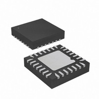
MCU AVR 5K FLASH 12MHZ 28-QFN
Manufacturer
Atmel
Series
AVR® ATtinyr
Specifications of ATTINY48-MMU
Core Processor
AVR
Core Size
8-Bit
Speed
12MHz
Connectivity
I²C, SPI
Peripherals
Brown-out Detect/Reset, POR, WDT
Number Of I /o
24
Program Memory Size
4KB (2K x 16)
Program Memory Type
FLASH
Eeprom Size
64 x 8
Ram Size
256 x 8
Voltage - Supply (vcc/vdd)
1.8 V ~ 5.5 V
Data Converters
A/D 6x10b
Oscillator Type
Internal
Operating Temperature
-40°C ~ 85°C
Package / Case
28-VQFN Exposed Pad, 28-HVQFN, 28-SQFN, 28-DHVQFN
Processor Series
ATTINY4x
Core
AVR8
Data Bus Width
8 bit
Data Ram Size
256 B
Interface Type
2-Wire, I2S, SPI
Maximum Clock Frequency
12 MHz
Number Of Programmable I/os
24
Number Of Timers
2
Maximum Operating Temperature
+ 85 C
Mounting Style
SMD/SMT
3rd Party Development Tools
EWAVR, EWAVR-BL
Development Tools By Supplier
ATAVRDRAGON, ATSTK500, ATSTK600, ATAVRISP2, ATAVRONEKIT
Minimum Operating Temperature
- 40 C
On-chip Adc
10 bit, 6 Channel
Package
28VQFN EP
Device Core
AVR
Family Name
ATtiny
Maximum Speed
12 MHz
Operating Supply Voltage
2.5|3.3|5 V
For Use With
ATAVRDRAGON - KIT DRAGON 32KB FLASH MEM AVR
Lead Free Status / RoHS Status
Lead free / RoHS Compliant


6.2.3
6.2.4
6.3
8008G–AVR–04/11
System Clock Prescaler
Internal 128 kHz Oscillator
Default Clock Source
When this oscillator is used as the chip clock, the Watchdog oscillator will still be used for the
Watchdog Timer and for the Reset Time-out. For more information on the pre-programmed cali-
bration value, see the section
When this oscillator is selected, start-up times are determined by the SUT Fuses as shown in
the table below.
Table 6-3.
Note:
The 128 kHz internal oscillator is a low power oscillator providing a clock of 128 kHz. The fre-
quency depends on supply voltage, temperature and patch variations. This clock may be
selected as the system clock by programming the CKSEL Fuses to “11”.
When this clock source is selected, start-up times are determined by the SUT Fuses as shown in
Table
Table 6-4.
Note:
The device is shipped with internal oscillator at 8.0 MHz and with the fuse CKDIV8 programmed,
resulting in 1.0 MHz system clock. The startup time is set to maximum and time-out period
enabled (CKSEL = 0b10, SUT = 0b10, CKDIV8 = 0). The default setting ensures that all users
can make their desired clock source setting using any available programming interface.
The ATtiny48/88 has a system clock prescaler, and the system clock can be divided by setting
the
system clock frequency and the power consumption when the requirement for processing power
SUT[1:0]
SUT[1:0]
“CLKPR – Clock Prescale Register” on page
10
00
01
11
00
01
10
11
6-4.
(2)
1. If the RSTDISBL fuse is programmed, this start-up time will be increased to 14CK + 4 ms to
2.
1. If the RSTDISBL fuse is programmed, this start-up time will be increased to 14CK + 4 ms to
The device is shipped with this option selected.
ensure programming mode can be entered.
ensure programming mode can be entered.
Power Conditions
BOD enabled
Fast rising power
Slowly rising power
Start-up Times for the Internal Calibrated Oscillator Clock Selection
Start-up Times for the 128 kHz Internal Oscillator
Power Conditions
BOD enabled
Fast rising power
Slowly rising power
“Calibration Byte” on page
from Power-down
from Power-down
Start-up Time
Start-up Time
6 CK
6 CK
6 CK
34. This feature can be used to decrease the
Reserved
Reserved
6 CK
6 CK
6 CK
190.
from Reset (V
ATtiny48/88
Additional Delay
Additional Delay
14CK + 64 ms
14CK + 4 ms
14CK + 64 ms
from Reset
14CK + 4 ms
14CK
14CK
(1)
CC
(1)
= 5.0V)
31
Related parts for ATTINY48-MMU
Image
Part Number
Description
Manufacturer
Datasheet
Request
R

Part Number:
Description:
Manufacturer:
Atmel Corporation
Datasheet:

Part Number:
Description:
MCU AVR 4K ISP FLASH 1.8V 32TQFP
Manufacturer:
Atmel
Datasheet:

Part Number:
Description:
MCU AVR 4K ISP FLASH 1.8V 32-QFN
Manufacturer:
Atmel
Datasheet:

Part Number:
Description:
MCU AVR 4K ISP FLASH 1.8V 28-DIP
Manufacturer:
Atmel
Datasheet:

Part Number:
Description:
MCU AVR 4KB FLASH 12MHZ 32TQFP
Manufacturer:
Atmel
Datasheet:
Part Number:
Description:
MCU AVR 4KB FLASH 12MHZ 32QFN
Manufacturer:
Atmel
Datasheet:

Part Number:
Description:
MCU AVR 4KB FLASH 12MHZ 28-VQFN
Manufacturer:
Atmel
Datasheet:
Part Number:
Description:
MCU AVR 4KB FLASH 12MHZ 28QFN
Manufacturer:
Atmel
Datasheet:
Part Number:
Description:
8-bit Microcontrollers - MCU 4KB FL,64B EE, 256B SRAM-12MHz
Manufacturer:
Atmel
Part Number:
Description:
8-bit Microcontrollers - MCU Microcontroller
Manufacturer:
Atmel
Part Number:
Description:
Manufacturer:
Atmel Corporation
Datasheet: