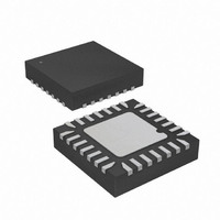
ATTINY48-MMU Atmel, ATTINY48-MMU Datasheet - Page 298

ATTINY48-MMU
Manufacturer Part Number
ATTINY48-MMU
Description
MCU AVR 5K FLASH 12MHZ 28-QFN
Manufacturer
Atmel
Series
AVR® ATtinyr
Specifications of ATTINY48-MMU
Core Processor
AVR
Core Size
8-Bit
Speed
12MHz
Connectivity
I²C, SPI
Peripherals
Brown-out Detect/Reset, POR, WDT
Number Of I /o
24
Program Memory Size
4KB (2K x 16)
Program Memory Type
FLASH
Eeprom Size
64 x 8
Ram Size
256 x 8
Voltage - Supply (vcc/vdd)
1.8 V ~ 5.5 V
Data Converters
A/D 6x10b
Oscillator Type
Internal
Operating Temperature
-40°C ~ 85°C
Package / Case
28-VQFN Exposed Pad, 28-HVQFN, 28-SQFN, 28-DHVQFN
Processor Series
ATTINY4x
Core
AVR8
Data Bus Width
8 bit
Data Ram Size
256 B
Interface Type
2-Wire, I2S, SPI
Maximum Clock Frequency
12 MHz
Number Of Programmable I/os
24
Number Of Timers
2
Maximum Operating Temperature
+ 85 C
Mounting Style
SMD/SMT
3rd Party Development Tools
EWAVR, EWAVR-BL
Development Tools By Supplier
ATAVRDRAGON, ATSTK500, ATSTK600, ATAVRISP2, ATAVRONEKIT
Minimum Operating Temperature
- 40 C
On-chip Adc
10 bit, 6 Channel
Package
28VQFN EP
Device Core
AVR
Family Name
ATtiny
Maximum Speed
12 MHz
Operating Supply Voltage
2.5|3.3|5 V
For Use With
ATAVRDRAGON - KIT DRAGON 32KB FLASH MEM AVR
Lead Free Status / RoHS Status
Lead free / RoHS Compliant
- Current page: 298 of 302
- Download datasheet (9Mb)
iv
ATtiny48/88
17 ADC – Analog to Digital Converter ..................................................... 164
18 debugWIRE On-Chip Debug System .................................................. 181
19 Self-Programming the Flash ............................................................... 183
20 Lock Bits, Fuse Bits and Device Signature ....................................... 188
21 External Programming ........................................................................ 191
17.1
17.2
17.3
17.4
17.5
17.6
17.7
17.8
17.9
17.10
17.11
17.12
17.13
18.1
18.2
18.3
18.4
18.5
18.6
19.1
19.2
20.1
20.2
20.3
20.4
21.1
21.2
21.3
21.4
Features ........................................................................................................164
Overview ........................................................................................................164
Operation .......................................................................................................165
Starting a Conversion ....................................................................................166
Prescaling and Conversion Timing ................................................................167
Changing Channel or Reference Selection ...................................................170
ADC Noise Canceler .....................................................................................171
Analog Input Circuitry ....................................................................................171
Analog Noise Canceling Techniques .............................................................172
ADC Accuracy Definitions .............................................................................173
ADC Conversion Result .................................................................................175
Temperature Measurement ...........................................................................175
Register Description ......................................................................................176
Features ........................................................................................................181
Overview ........................................................................................................181
Physical Interface ..........................................................................................181
Software Break Points ...................................................................................182
Limitations of debugWIRE .............................................................................182
Register Description ......................................................................................182
Addressing the Flash During Self-Programming ...........................................184
Register Description ......................................................................................186
Lock Bits ........................................................................................................188
Fuse Bits ........................................................................................................189
Signature Bytes .............................................................................................190
Calibration Byte .............................................................................................190
Memory Parametrics .....................................................................................191
Parallel Programming ....................................................................................191
Serial Programming .......................................................................................200
Programming Time for Flash and EEPROM .................................................205
8008G–AVR–04/11
Related parts for ATTINY48-MMU
Image
Part Number
Description
Manufacturer
Datasheet
Request
R

Part Number:
Description:
Manufacturer:
Atmel Corporation
Datasheet:

Part Number:
Description:
MCU AVR 4K ISP FLASH 1.8V 32TQFP
Manufacturer:
Atmel
Datasheet:

Part Number:
Description:
MCU AVR 4K ISP FLASH 1.8V 32-QFN
Manufacturer:
Atmel
Datasheet:

Part Number:
Description:
MCU AVR 4K ISP FLASH 1.8V 28-DIP
Manufacturer:
Atmel
Datasheet:

Part Number:
Description:
MCU AVR 4KB FLASH 12MHZ 32TQFP
Manufacturer:
Atmel
Datasheet:

Part Number:
Description:
MCU AVR 4KB FLASH 12MHZ 32QFN
Manufacturer:
Atmel
Datasheet:

Part Number:
Description:
MCU AVR 4KB FLASH 12MHZ 28-VQFN
Manufacturer:
Atmel
Datasheet:

Part Number:
Description:
MCU AVR 4KB FLASH 12MHZ 28QFN
Manufacturer:
Atmel
Datasheet:

Part Number:
Description:
8-bit Microcontrollers - MCU 4KB FL,64B EE, 256B SRAM-12MHz
Manufacturer:
Atmel

Part Number:
Description:
8-bit Microcontrollers - MCU Microcontroller
Manufacturer:
Atmel

Part Number:
Description:
Manufacturer:
Atmel Corporation
Datasheet:


