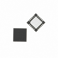
C8051F537-IM Silicon Laboratories Inc, C8051F537-IM Datasheet - Page 105

C8051F537-IM
Manufacturer Part Number
C8051F537-IM
Description
IC 8051 MCU 2K FLASH 20QFN
Manufacturer
Silicon Laboratories Inc
Series
C8051F53xr
Specifications of C8051F537-IM
Core Processor
8051
Core Size
8-Bit
Speed
25MHz
Connectivity
SPI, UART/USART
Peripherals
Brown-out Detect/Reset, POR, PWM, Temp Sensor, WDT
Number Of I /o
16
Program Memory Size
2KB (2K x 8)
Program Memory Type
FLASH
Ram Size
256 x 8
Voltage - Supply (vcc/vdd)
2 V ~ 5.25 V
Data Converters
A/D 16x12b
Oscillator Type
Internal
Operating Temperature
-40°C ~ 125°C
Package / Case
20-QFN
Data Bus Width
8 bit
Data Ram Size
256 B
Interface Type
SPI, UART
Maximum Clock Frequency
25 MHz
Number Of Programmable I/os
16
Number Of Timers
3
Operating Supply Voltage
2.7 V to 5.25 V
Maximum Operating Temperature
+ 125 C
Mounting Style
SMD/SMT
Minimum Operating Temperature
- 40 C
On-chip Adc
12 bit, 16 Channel
Lead Free Status / RoHS Status
Lead free / RoHS Compliant
Eeprom Size
-
Lead Free Status / Rohs Status
Details
Other names
336-1400
Available stocks
Company
Part Number
Manufacturer
Quantity
Price
Company:
Part Number:
C8051F537-IM
Manufacturer:
Silicon Labs
Quantity:
135
- Current page: 105 of 218
- Download datasheet (2Mb)
SFR Definition 10.5. IT01CF: INT0/INT1 Configuration
Bit 7:
Bits 6–4: IN1SL2–0: INT0 Port Pin Selection Bits
Bit 3:
Bits 2–0: INT0SL2–0: INT0 Port Pin Selection Bits
Note: Refer to SFR Definition 18.1. “TCON: Timer Control” on page 185 for INT0/1 edge- or level-sensitive interrupt selection.
IN1PL
R/W
Bit7
IN1PL: INT0 Polarity
0: INT0 input is active low.
1: INT0 input is active high.
These bits select which Port pin is assigned to INT0. Note that this pin assignment is inde-
pendent of the Crossbar; INT0 will monitor the assigned Port pin without disturbing the
peripheral that has been assigned the Port pin via the Crossbar. The Crossbar will not
assign the Port pin to a peripheral if it is configured to skip the selected pin (accomplished by
setting to 1 the corresponding bit in register P0SKIP).
IN0PL: INT0 Polarity
0: INT0 interrupt is active low.
1: INT0 interrupt is active high.
These bits select which Port pin is assigned to INT0. Note that this pin assignment is inde-
pendent of the Crossbar. INT0 will monitor the assigned Port pin without disturbing the
peripheral that has been assigned the Port pin via the Crossbar. The Crossbar will not
assign the Port pin to a peripheral if it is configured to skip the selected pin (accomplished by
setting to 1 the corresponding bit in register P0SKIP).
Note: Available in the C80151F53x/C8051F53xA parts.
Note: Available in the C80151F53x/C8051F53xA parts.
IN1SL2
R/W
Bit6
IN1SL2-0
IN0SL2-0
000
001
010
100
101
000
001
010
100
101
011
110
111
011
110
111
IN1SL1
R/W
Bit5
IN1SL0
C8051F52x/F52xA/F53x/F53xA
R/W
Bit4
INT1 Port Pin
INT0 Port Pin
P0.6*
P0.7*
P0.6*
P0.7*
P0.0
P0.1
P0.2
P0.3
P0.4
P0.5
P0.0
P0.1
P0.2
P0.3
P0.4
P0.5
Rev. 1.3
IN0PL
R/W
Bit3
IN0SL2
R/W
Bit2
IN0SL1
R/W
Bit1
SFR Address:
IN0SL0
R/W
Bit0
00000001
Reset Value
0xE4
105
Related parts for C8051F537-IM
Image
Part Number
Description
Manufacturer
Datasheet
Request
R
Part Number:
Description:
SMD/C°/SINGLE-ENDED OUTPUT SILICON OSCILLATOR
Manufacturer:
Silicon Laboratories Inc
Part Number:
Description:
Manufacturer:
Silicon Laboratories Inc
Datasheet:
Part Number:
Description:
N/A N/A/SI4010 AES KEYFOB DEMO WITH LCD RX
Manufacturer:
Silicon Laboratories Inc
Datasheet:
Part Number:
Description:
N/A N/A/SI4010 SIMPLIFIED KEY FOB DEMO WITH LED RX
Manufacturer:
Silicon Laboratories Inc
Datasheet:
Part Number:
Description:
N/A/-40 TO 85 OC/EZLINK MODULE; F930/4432 HIGH BAND (REV E/B1)
Manufacturer:
Silicon Laboratories Inc
Part Number:
Description:
EZLink Module; F930/4432 Low Band (rev e/B1)
Manufacturer:
Silicon Laboratories Inc
Part Number:
Description:
I°/4460 10 DBM RADIO TEST CARD 434 MHZ
Manufacturer:
Silicon Laboratories Inc
Part Number:
Description:
I°/4461 14 DBM RADIO TEST CARD 868 MHZ
Manufacturer:
Silicon Laboratories Inc
Part Number:
Description:
I°/4463 20 DBM RFSWITCH RADIO TEST CARD 460 MHZ
Manufacturer:
Silicon Laboratories Inc
Part Number:
Description:
I°/4463 20 DBM RADIO TEST CARD 868 MHZ
Manufacturer:
Silicon Laboratories Inc
Part Number:
Description:
I°/4463 27 DBM RADIO TEST CARD 868 MHZ
Manufacturer:
Silicon Laboratories Inc
Part Number:
Description:
I°/4463 SKYWORKS 30 DBM RADIO TEST CARD 915 MHZ
Manufacturer:
Silicon Laboratories Inc
Part Number:
Description:
N/A N/A/-40 TO 85 OC/4463 RFMD 30 DBM RADIO TEST CARD 915 MHZ
Manufacturer:
Silicon Laboratories Inc
Part Number:
Description:
I°/4463 20 DBM RADIO TEST CARD 169 MHZ
Manufacturer:
Silicon Laboratories Inc


