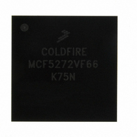
MCF5272VF66 Freescale Semiconductor, MCF5272VF66 Datasheet - Page 287

MCF5272VF66
Manufacturer Part Number
MCF5272VF66
Description
IC MPU 32BIT 66MHZ 196-MAPBGA
Manufacturer
Freescale Semiconductor
Series
MCF527xr
Specifications of MCF5272VF66
Core Processor
Coldfire V2
Core Size
32-Bit
Speed
66MHz
Connectivity
EBI/EMI, Ethernet, I²C, SPI, UART/USART, USB
Peripherals
DMA, WDT
Number Of I /o
32
Program Memory Size
16KB (4K x 32)
Program Memory Type
ROM
Ram Size
1K x 32
Voltage - Supply (vcc/vdd)
3 V ~ 3.6 V
Oscillator Type
External
Operating Temperature
0°C ~ 70°C
Package / Case
196-MAPBGA
Lead Free Status / RoHS Status
Contains lead / RoHS non-compliant
Eeprom Size
-
Data Converters
-
Available stocks
Company
Part Number
Manufacturer
Quantity
Price
Company:
Part Number:
MCF5272VF66
Manufacturer:
HYNIX
Quantity:
19
Company:
Part Number:
MCF5272VF66
Manufacturer:
FREESCAL
Quantity:
885
Company:
Part Number:
MCF5272VF66
Manufacturer:
Freescale Semiconductor
Quantity:
10 000
Part Number:
MCF5272VF66
Manufacturer:
FREESCALE
Quantity:
20 000
Company:
Part Number:
MCF5272VF66J
Manufacturer:
Freescale
Quantity:
256
Company:
Part Number:
MCF5272VF66J
Manufacturer:
Freescale Semiconductor
Quantity:
10 000
Company:
Part Number:
MCF5272VF66R2
Manufacturer:
Freescale Semiconductor
Quantity:
10 000
Company:
Part Number:
MCF5272VF66R2J
Manufacturer:
Freescale Semiconductor
Quantity:
10 000
- Current page: 287 of 544
- Download datasheet (7Mb)
A device may support multiple configurations. Within any one configuration, the device may support
multiple interfaces. An interface consists of a set of endpoints that presents to the host a single feature or
function of the device. An interface within a configuration may have alternate settings that redefine the
characteristics of the associated endpoints. All devices must provide a device descriptor and at least one
configuration, interface and endpoint descriptor. Each configuration must have at least one interface and
one endpoint descriptor. Only one configuration is effective at any time, but several interfaces and their
related endpoints may be operational at the same time. Only one setting for a particular interface is
effective at any time.
12.3.3.2
The example descriptor structure in
to Chapter 9 of the USB Specification for information on the contents of each descriptor.
This example is described in the configuration RAM sequence shown below. The device descriptor begins
at address MBAR + 0x1400. Each descriptor must immediately follow the previous descriptor without any
empty locations between them.
Freescale Semiconductor
1. Device Descriptor
2. Configuration #1 Descriptor
3. Interface #0 Descriptor
4. Endpoint #1 Descriptor
5. Endpoint #2 Descriptor
6. Interface #1 Descriptor
7. Endpoint #3 Descriptor
8. Configuration #2 Descriptor
Endpoint #1
Descriptor
USB Device Configuration Example
Interface #0
Descriptor
Figure 12-23. Example USB Configuration Descriptor Structure
MCF5272 ColdFire
Endpoint #2
Descriptor
Configuration #1
Descriptor
Figure 12-23
®
Interface #1
Endpoint #3
Descriptor
Descriptor
Integrated Microprocessor User’s Manual, Rev. 3
Descriptor
Device
shows a device with three different configurations. Refer
Configuration #2
Endpoint #1
Interface #0
Descriptor
Descriptor
Descriptor
Endpoint #1
Descriptor
Configuration #3
Interface #0
Descriptor
Descriptor
Universal Serial Bus (USB)
Endpoint #2
Descriptor
12-29
Related parts for MCF5272VF66
Image
Part Number
Description
Manufacturer
Datasheet
Request
R
Part Number:
Description:
Mcf5272 Coldfire Integrated Microprocessor User
Manufacturer:
Freescale Semiconductor, Inc
Datasheet:

Part Number:
Description:
MCF5272 Interrupt Service Routine for the Physical Layer Interface Controller
Manufacturer:
Freescale Semiconductor / Motorola
Datasheet:
Part Number:
Description:
Manufacturer:
Freescale Semiconductor, Inc
Datasheet:
Part Number:
Description:
Manufacturer:
Freescale Semiconductor, Inc
Datasheet:
Part Number:
Description:
Manufacturer:
Freescale Semiconductor, Inc
Datasheet:
Part Number:
Description:
Manufacturer:
Freescale Semiconductor, Inc
Datasheet:
Part Number:
Description:
Manufacturer:
Freescale Semiconductor, Inc
Datasheet:
Part Number:
Description:
Manufacturer:
Freescale Semiconductor, Inc
Datasheet:
Part Number:
Description:
Manufacturer:
Freescale Semiconductor, Inc
Datasheet:
Part Number:
Description:
Manufacturer:
Freescale Semiconductor, Inc
Datasheet:
Part Number:
Description:
Manufacturer:
Freescale Semiconductor, Inc
Datasheet:
Part Number:
Description:
Manufacturer:
Freescale Semiconductor, Inc
Datasheet:
Part Number:
Description:
Manufacturer:
Freescale Semiconductor, Inc
Datasheet:
Part Number:
Description:
Manufacturer:
Freescale Semiconductor, Inc
Datasheet:
Part Number:
Description:
Manufacturer:
Freescale Semiconductor, Inc
Datasheet:


