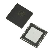
AS3991-BQFT austriamicrosystems, AS3991-BQFT Datasheet - Page 14

AS3991-BQFT
Manufacturer Part Number
AS3991-BQFT
Description
IC UHF RFID READER 64-QFN
Manufacturer
austriamicrosystems
Specifications of AS3991-BQFT
Rf Type
Read / Write
Frequency
840MHz ~ 960MHz
Features
ISO-18000-6
Package / Case
64-VFQFN, Exposed Pad
Lead Free Status / RoHS Status
Lead free / RoHS Compliant
Other names
AS3991-BQFT
AS3991-BQFTTR
AS3991-BQFTTR
AS3990/AS3991
Data Sheet - D e t a i l e d D e s c r i p t i o n
Hopping to the second frequency is triggered, if direct command ‘Hop to auxiliary frequency’ is sent. Hop to the third
frequency is similar: the register ‘PLL A/B divider main (16)’ can be written any time the external system has free
resources and actual hop is triggered by direct command ‘Hop to main frequency’.
Chip Status Control
In the ‘Chip status control register’ (00)
(see Table
13), main functionality of the chip is defined. By setting the rf_on bit
in the ’Chip control register’ (00), the transmit and receive part are enabled. The initial RF field ramp-up is defined with
the Tari1:0 option bits in the ‘Protocol control register’ (01)
(see Table
14). It is also possible to slow down the initial RF
field ramp by option bits trfon1:0 in the ‘Modulator control register’ (15)
(see Table
34). The available values are 100µs,
200µs, and 400µs.
The host system can check whether the field ramp-up is finished via the rf_ok bit in the ‘AGC and internal status
register’ (0E)
(see Table
27), which is set high when ramp-up is finished. By setting the rf_on bit low, the field will ramp-
down similarly to the ramp-up transient. It is also possible to enable receiver operation by setting rec_on bit. The
agc_on and agl_on bits enables the (Automatic Gain Control) AGC and (Automatic Gain Leveling) AGL functionality,
dac_on enables DA converter, bit direct enables the direct data mode, and stby bit moves chip to the stand-by power
mode.
Protocol Control
In the ‘Protocol control register’ (01)
(see Table
14), the main protocol parameters are selected (Tari value and RX
coding for EPC Gen2 protocol). The Gen2 Protocol is configured by setting Prot<1:0> bits to low. The dir_mode<6> bit
defines type of output signals in case the direct mode is used. The rx_crc_n<7> bit high defines reception in case the
user does not want to check CRC internally. In this case, the CRC is not checked but is just passed to the FIFO like
other data bytes. In the EPC Gen2, this function is useful in case of truncated EPC reply where the ‘CRC’ transponder
transmits is not valid CRC calculated over actual transmitted data.
Option Registers Preset
After power up (EN low to high transition), the option registers are preset to values that allow default reader operation.
Default transmission uses Tari 25µs, PW length is 0.5Tari, TX one length is 2 Tari, and RTcal is 133µs. Default
reception uses FM0 coding with long preamble, link frequency 160kHz. Default operation is set to internal PLL with
internal VCO, differential input mixers, low power output (RFOPX, RFONX), and DSB-ASK transmit modulation.
Transmitter
Transmitter section comprises of protocol processing digital part, shaping, modulator and amplifier circuitry. The RF
carrier is modulated with the transmit data and amplified for transmission.
Normal Mode
In normal mode, all signal processing (protocol coding, adding preamble or frame-sync and CRC, signal shaping, and
modulation) is done internally.
The external system (MCU) triggers the transmission and loads the transmit data into the FIFO register. The
transmission is started by sending the transmit command followed by information on the number of bytes that should
be transmitted and the data. The number of bytes needs to be written in the ‘TX length’ registers and the data to the
FIFO register. Both can be done by a single continuous write. The transmission actually starts when the first data byte
is written into the FIFO.
The second possibility is to start transmission with one of the direct Gen2 commands (Query, QueryRep, QueryAdjust,
ACK, NAK, ReqRN). In this case, the transmission is started after receiving the command.
In case the transmission data length is longer than the size of the FIFO, the host system (MCU) should initially fill the
FIFO register with up to 24 bytes. The reader chip starts transmission and sends an interrupt request when only 3
bytes are left in the FIFO. When interrupt is received, the host system needs to read the ‘IRQ status register’ (0C)
(see
Table
25). By reading this register, the host system is notified by the cause of the interrupt and the same reading also
clears the interrupt. In case the cause of the interrupt is low FIFO level and the host system did not put all data to the
FIFO, the remaining data needs to be sent to FIFO, again according to the available FIFO size. In case all transmission
data was already sent to the FIFO, the host system waits until the transmission runs out. At the end of the transmit
operation, the external system is notified by another interrupt request with a flag in the IRQ register that signals the end
of transmission.
www.austriamicrosystems.com
Revision 3.81
14 - 51


