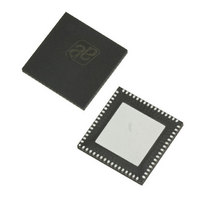
AS3991-BQFT austriamicrosystems, AS3991-BQFT Datasheet - Page 41

AS3991-BQFT
Manufacturer Part Number
AS3991-BQFT
Description
IC UHF RFID READER 64-QFN
Manufacturer
austriamicrosystems
Specifications of AS3991-BQFT
Rf Type
Read / Write
Frequency
840MHz ~ 960MHz
Features
ISO-18000-6
Package / Case
64-VFQFN, Exposed Pad
Lead Free Status / RoHS Status
Lead free / RoHS Compliant
Other names
AS3991-BQFT
AS3991-BQFTTR
AS3991-BQFTTR
AS3990/AS3991
Data Sheet - A p p l i c a t i o n I n f o r m a t i o n
QueryAdjustNic (9B)
The QueryAdjustNic command issues the command QueryAdjust followed by two session bits and ‘no change’
parameter. The session bits are taken from ‘TX options’ (02) register. The received RN16 is stored in an internal
register for further communication (ACK). RN 16 is also achievable from the FIFO.
QueryAdjustDown (9C)
The QueryAdjustUp command issues the command QueryAdjust followed by two session bits and ‘down’ parameter
(decrease number of slots Q). The session bits are taken from ‘TX options’ (02) register. The received RN16 is stored
in an internal register for further communication (ACK, ReqRN). RN 16 is also achievable from the FIFO.
ACK (9D)
The ACK command issues the command followed by RN16 (or handle) that was stored in the internal register. The
stored RN16 was acquired in last successful Query command.
NAK (9E)
The direct NAK command issues the NAK command to tags.
ReqRN (9F)
The direct ReqRN command issues the ReqRN command to the tag. The last received RN is used as a parameter and
the received new RN16 (handle) is stored in an internal register for further communication (ACK, ReqRN…). New RN
16 is also achievable from the FIFO.
Reader Communication Interface
The basic interface is a parallel 10-pin bus, which can be also configured and used as a serial peripheral interface
(SPI) also. Both modes are exclusive and one can not switch between them in a single application. The parallel mode
is selected if all IO pins are low during low to high transition of the EN pin (enable).
When the serial interface is selected in an application, the unused IO1 and IO0 pins should be hard wired accordingly
as given in
as given in
The reader will always behave as the “slave” connected to the host system (MCU), which behaves as the “master”
device. The host system initiates all communications with the reader and is used for communication to the higher
levels towards the host station, which can typically be a personal computer. The reader has an IRQ pin to ask for host
system attention.
Table 45. Pin Assignment in Parallel and Serial Interface Connection and in Case of Direct Mode
www.austriamicrosystems.com
Table
Table 45
CLK
Pin
IO7
IO6
IO5
IO4
IO3
IO2
IO1
45. Upon power-up (EN low to high transition), the reader looks for the status of these three pins and
it enters parallel or serial mode.
CLK
A/D[7]
A/D[6],
Direct mode out (sub-carrier)
A/D[5],
Direct mode out (sub-carrier)
A/D[4]
A/D[3]
Direct mode modulation input
A/D[2]
Direct mode enable RX input
A/D[1]
Parallel normal mode,
Direct mode
Revision 3.81
SCLK from master
MOSI
MISO
Direct mode out (sub-carrier)
Direct mode out (sub-carrier)
SS – Slave Select
Direct mode modulation input
Direct mode enable RX input
Hard wire to VDD_IO
2
3
(data in)
(data out),
SPI with SS
Direct mode
1
,
41 - 51


