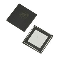
AS3991-BQFT austriamicrosystems, AS3991-BQFT Datasheet - Page 43

AS3991-BQFT
Manufacturer Part Number
AS3991-BQFT
Description
IC UHF RFID READER 64-QFN
Manufacturer
austriamicrosystems
Specifications of AS3991-BQFT
Rf Type
Read / Write
Frequency
840MHz ~ 960MHz
Features
ISO-18000-6
Package / Case
64-VFQFN, Exposed Pad
Lead Free Status / RoHS Status
Lead free / RoHS Compliant
Other names
AS3991-BQFT
AS3991-BQFTTR
AS3991-BQFTTR
AS3990/AS3991
Data Sheet - A p p l i c a t i o n I n f o r m a t i o n
Where:
Start = start condition
Adr = address with Cont bit low
Adrc = address with the Cont bit high
Cmd = command byte
Data = data byte
StopSgl = stop condition for termination of the command or non-continuous address mode
StopCont = stop condition for termination of the continuous address mode
There are also combinations of different communication modes allowed in a single stream between the start and stop
condition. Some examples of combined communication are presented below:
Non-continuous Address Mode and Command Mode
Command and Continuous Address Mode
Non-continuous, Command, and Continuous Address Mode
Non-continuous address mode and Command mode can be continued by any mode including the Continuous address
mode. The Continuous address mode should be terminated by StopCont condition. Changing from Continuous
address mode to the other two modes can be done only by StopCont condition followed by start condition.
Majority of the registers in the reader IC are 8-bit long. They can be accessed by continuous or non-continuous
address mode.
Registers 12, 14, 15, 16, and 17 are three bytes deep. They can be accessed by Continuous address mode only. The
least significant byte is accessed first. It is possible to access only deep register in a single communication stream,
more of them, or combination of normal and deep registers. Example is presented below:
1. Least significant byte
2. Middle byte
3. Most significant byte
Continuous access is possible for registers 00 to the end of the register 12. Register 13 is deep register and prevents
continuous access over it to register 14. Continuous access is again possible from register 14 to the end of FIFO
(address 1F).
The 24 bytes deep FIFO register can be accessed by Continuous address mode only. It is allowed to use
communication stream combined of command mode and address mode. Example is combination needed for
transmission composed of Reset FIFO, Transmit, write to 1D, 1E for transmission length, and continuously to 1F for
filling FIFO with transmission data.
Parallel Interface Communication
In parallel mode, the Start condition is triggered by rising edge of the IO7 pin while the CLK pin is high. This is used to
reset the interface logic. Communication is terminated by StopSgl condition or StopCont condition. StopSgl condition is
triggered by falling edge on IO7 pin while CLK pin is high. StopCont condition is triggered by successive rising and
falling edge on IO7 pin while CLK is low. The ‘StopSgl’ condition is also used to terminate the direct mode.
www.austriamicrosystems.com
Start
Start ResetFIFO Transmit Write Cont. to 1D Data (1D) Data (1E) Data FIFO (0) Data FIFO (1) … StopCont
Start
Start
Start
Adr x
Adr x
Cmd x
8F
Data (x)
Data (x)
90
Cmd y
Adrc x
…
Cmd y
Adr y
3D
…
Data0 (x)
…
Adrc z
Data (y)
Adrc z
1
Revision 3.81
TX length
Data (z)
Data (z)
Data1 (x)
…
Data (z+1)
Data (z+1)
2
Cmd z
Data2 (x)
…
TX data
…
Data (z+n)
3
Cmd w
Data (z+n)
StopCont
…
StopSgl
StopCont
StopSgl
43 - 51


