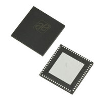
AS3991-BQFT austriamicrosystems, AS3991-BQFT Datasheet - Page 18

AS3991-BQFT
Manufacturer Part Number
AS3991-BQFT
Description
IC UHF RFID READER 64-QFN
Manufacturer
austriamicrosystems
Specifications of AS3991-BQFT
Rf Type
Read / Write
Frequency
840MHz ~ 960MHz
Features
ISO-18000-6
Package / Case
64-VFQFN, Exposed Pad
Lead Free Status / RoHS Status
Lead free / RoHS Compliant
Other names
AS3991-BQFT
AS3991-BQFTTR
AS3991-BQFTTR
AS3990/AS3991
Data Sheet - D e t a i l e d D e s c r i p t i o n
Receiver
Receiver section comprises two input mixers followed by gain and filtering stages. The two receiving signals are fed to
decision circuitry, bit decoder and framer where preamble is removed and CRC is checked. The clean framed data is
accessible to the host system (MCU) via. 24 byte FIFO.
Input Mixer
The two input mixers are driven with 90º shifted LO signals and form IQ demodulator circuit. Using IQ architecture, the
amplitude modulated input signals are demodulated in the in-phase channel (I) while the phase modulated input
signals are demodulated in the quadrature phase (Q) channel. Mixed input modulation is demodulated in both
receiving channels. This configuration allows reliable operation regardless the transponders. Modulation presents
amplitude or phase modulation at receiver’s input and suppresses communication holes that are caused by modulation
alternation.
To optimize the receiver’s noise and input range properties, the mixers have adjustable input range. Depending on the
reflectivity of the environment or antenna, the receiver’s input RF voltage can increase to a level that corrupts mixer
operation. In such a case, the input range can be widened by internal input attenuator setting option bit ir<0>.
In case lower supply voltage is used, the ir<1> option bit adapts mixer’s operation point to decreased supply. The
ir<1:0> bits are in the ‘RX special setting2 register’ (0A)
with 4.8V VDD_MIX supply (option bit low_vext=0) and accordingly high VEXT voltage.
By default differential mixers input is chosen. The differential input is formed by pins MIX_INP and MIX_INN. Input
should be AC coupled. Besides a differential input, it is possible to use single ended mixers input. It is chosen by s_mix
bit in the ‘Rx special setting registers’ (0A)
AC coupled also. The unused input doesn’t need to be connected.
RX Filter
The high pass filter corner frequency is adjustable in the range between 6 kHz and 150 kHz. Filter low pass corner
frequency is adjustable in the range between 160 kHz and 1200 kHz. The appropriate combinations for different link
are selected by the lf<2:1> option bits in the ‘RX special setting’ (09) register. The following table presents typical filter
characteristics.
For the better reception of the FM0 coded signals, it is possible to decrease the high pass corner frequency by the
factor of two by option bit fl<3>. This improves passthrough of the FM0 preamble.
It is possible to additionally speed up the first AC coupling time constant by setting option bit fl<4> in the ‘RX special
setting’ (09) register
The internal (patent pending) feedback AC coupling system prior to the start of transmit modulation stores the DC
operating points and after data transmission progressively adjusts the high pass time constant to allow very fast
settling time prior to beginning of reception. Such system is needed to accommodate the short TX to RX time used at
the highest bit rates in the EPC Gen-2 protocol.
www.austriamicrosystems.com
Higher output power output (~20dBm) can be used for antenna driving in case of short range applications.
Internal higher power amplifier
24). For operation it needs external RF choke and correct impedance matching for operation in 50Ω system. It is
also possible to use differential output by setting etx<4>. The differential outputs are RFOUTP_1, RFOUTP_2 and
RFOUTN_1, RFOUTN_2. Single ended output is RFOUTN_1, RFOUTN_2.
2. Internal PA is available on AS3991only.
fl<2:1>
00
01
10
11
(see Table
3dB bandwidth
145 – 1200kHz
6.5 –160kHz
20 – 320kHz
55 – 830kHz
22).
2
is enabled by etx<3:2> bits in the ‘Regulator an IO control’ (0B) register
(see Table
Attenuation at 10kHz
Revision 3.81
23). The single ended mixers input MIXS_IN pin. Input should be
(see Table
16dB
24dB
7dB
NA
23). Single ended input mixer should be used only
Attenuation at
600kHz
17dB
9dB
NA
NA
Attenuation at
1200kHz
31dB
20dB
6dB
NA
(see Table
18 - 51


