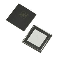
AS3991-BQFT austriamicrosystems, AS3991-BQFT Datasheet - Page 42

AS3991-BQFT
Manufacturer Part Number
AS3991-BQFT
Description
IC UHF RFID READER 64-QFN
Manufacturer
austriamicrosystems
Specifications of AS3991-BQFT
Rf Type
Read / Write
Frequency
840MHz ~ 960MHz
Features
ISO-18000-6
Package / Case
64-VFQFN, Exposed Pad
Lead Free Status / RoHS Status
Lead free / RoHS Compliant
Other names
AS3991-BQFT
AS3991-BQFTTR
AS3991-BQFTTR
AS3990/AS3991
Data Sheet - A p p l i c a t i o n I n f o r m a t i o n
Table 45. Pin Assignment in Parallel and Serial Interface Connection and in Case of Direct Mode
1. SS – Slave Select pin active low
2. MOSI – Master Output, Slave Input
3. MISO – Master Input, Slave Output
Communication is initialized by a Start condition, which should be followed by an Address or Command word. The
Address and Command words are 8-bits long. Their format is shown in
appropriate stop condition. Three different communication modes are available – Continuous address mode, non-
continuous address mode, and command mode. Continuous address mode needs to be closed by StopCont condition,
while the other two modes need to be terminated by StopSgl condition.
Table 46. Address / Command Word Bit Distribution
The MSB (Bit 7) determines if the word is to be used as a command or address. The last two columns in
the function of the separate bits in the event that either address or command is written. Data is expected once the
address word is sent. In the event of continuous address mode (Cont mode=1), the first data that follows the address
is written (or read) to (from) the given address. For each additional data, the address is incremented by one. This
continuous mode can be used to write part of the control registers in a single stream without changing the address: for
instance, set-up of the pre-defined standard control registers from the MCU’s non-volatile memory to the reader. In the
case of non-continuous address, only one data word is expected after the address. The two address modes are used
to write or read the configuration registers or the FIFO. When writing or reading more than one byte the Continuous
address mode should be used. The Command mode is used to enter a command resulting in reader action (initialize
transmission, frequency hop…). Examples of expected communication between MCU and reader chip are shown
below:
Continuous Address Mode
Non-continuous Address Mode (Single Address Mode)
Command Mode
www.austriamicrosystems.com
Start
Start
Start
Bit
7
6
5
4
3
2
1
0
Adrc x
IRQ
Pin
IO0
Adr x
Data (x)
Continuous address mode
Address/Command bit 4
Address/Command bit 3
Address/Command bit 2
Address/Command bit 1
Address/Command bit 0
Cmd x
Command control bit
Data (x)
Description
Read/Write
A/D[0]
IRQ interrupt
Data (x+1)
Parallel normal mode,
Adr y
Direct mode
Data (x+2)
Cmd y
1=Cont., 0=Non-cont mode
Data (y)
Revision 3.81
0=Address, 1=Command
1=Read, 0=Write
Data (x+3)
Bit Function
…
Table
Hard wire to ground
IRQ interrupt
Data (x+4)
…
45. Communication is closed by an
Adr z
Address
…
SPI with SS
Direct mode
Adr 4
Adr 3
Adr 2
Adr 1
Adr 0
Cont
R/W
0
Data (z)
Data (x+n)
StopSgl
1
,
Table 46
Command
Not used
Not used
Cmd 4
Cmd 3
Cmd 2
Cmd 1
Cmd 0
StopSgl
StopCont
1
42 - 51
show


