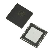
AS3991-BQFT austriamicrosystems, AS3991-BQFT Datasheet - Page 15

AS3991-BQFT
Manufacturer Part Number
AS3991-BQFT
Description
IC UHF RFID READER 64-QFN
Manufacturer
austriamicrosystems
Specifications of AS3991-BQFT
Rf Type
Read / Write
Frequency
840MHz ~ 960MHz
Features
ISO-18000-6
Package / Case
64-VFQFN, Exposed Pad
Lead Free Status / RoHS Status
Lead free / RoHS Compliant
Other names
AS3991-BQFT
AS3991-BQFTTR
AS3991-BQFTTR
AS3990/AS3991
Data Sheet - D e t a i l e d D e s c r i p t i o n
The two ‘TX length’ registers support in-complete bytes transmission. The high two nibbles in register 1D and the
nibble composed of bits B4 ~ B7 in ‘TX length byte 2’ (1E) register
that should be transmitted. Bit B0 (in register 1E) is a flag that signals the presence of additional bits that do not form a
complete byte. The number of bits are stored in bits B1~B3 of the same register (1E).
The protocol selection is done by the ‘Protocol control register’ (01)
the reader automatically adds all the special signals like Preamble, Frame-Sync, and CRC bytes. The data is then
coded to the modulation pulse level and sent to the modulator. This means that the external system only has to load
the FIFO with data and all the micro-coding is done automatically.
The EPC Gen 2 protocol allows some adjustment in transmission parameters. The reader IC supports three Tari
values (25µs, 12.5µs, 6.25µs) by changing Tari<1:0> option bits in the ‘Protocol control register’ (01). PW length and
length of the logical one in the transmission protocol can be adjusted by TxPW<1:0> and TxOne<1:0> option bits in the
‘TX options‘ (02) register. Session that should be used in direct commands is defined in the S1and S0 bits in the same
register. The back scatter link frequency is defined by TRcal in the Query command transmission. The TRcal is defined
by option bits TRcal<11:0> in the ‘TRcal registers’ (04, 05).
Table 6. Register Bits Settings
The software designer needs to take care that actual TRcal (reg. 04, 05) and RxLF<3:0> (reg. 03) bits and DR bit in the
transmission of the Query command are matched. Precise description is in the EPC Gen2 or ISO18000-6C protocol
description.
The Transmit section contains a timer. The timer is used to issue a command in a specified time window after a
transponder’s response. The timer’s time is defined in ‘TX replay in slot’ (06) register. The timer is enabled by using the
command ‘Delayed transmission without CRC’ (92) or ‘Delayed transmission with CRC’ (93) and is actually started at
the end of the reception.
Table 7. EPC_gen2 - Tari Combinations
www.austriamicrosystems.com
TARI
PW length
control
Data1 Tx
Coding
Link frequency
Protocol
setting
213.3
(kHz)
160
256
320
Zero and one length (RT CAL)
LF
40
80
Protocol
control<1:0>
TX option
<7:6>
TX option
<5:4>
Protocol
control<4:3>
RX option
<7:4>
Register
Bits
TARI settings
Division
Ratio
64/3
64/3
64/3
64/3
8
8
6,25µs (00)
0,27TARI
(00)
1,5TARI(00) 1,66TARI(01)
FMO(00)
40 kHz
(0000)
(microseconds)
200.00
100.00
133.33
100.02
TR cal
83.33
66.67
0,35TARI(01)
M2(01)
80 kHz
(0011)
2.1333
1.6003
1.3333
Revision 3.81
2.5
3.2
1.6
-
12,5µs (01)
160 kHz
(0110)
25µs
2.6667
1.3333
1.7778
1.3335
1.1111
Individual settings
3
-
(see Table 43)
(see Table
0,44TARI(10)
1,83TARI(10)
M4(10)
213,3 kHz
(1000)
2.6667
2.1333
2.5
-
-
-
-
14). As defined by selected protocol,
12.5µs
store the number of complete bytes
25µs
256 kHz
(1001)
2.2222
1.7778
3
-
-
-
-
0,5TARI(11)
2TARI(11)
M8(11)
320 kHz
(1100)
2.5
-
-
-
-
-
-
6.25µs
640 kHz
(1111)
15 - 51
3
-
-
-
-
-
-


