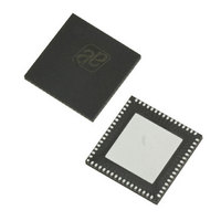
AS3991-BQFT austriamicrosystems, AS3991-BQFT Datasheet - Page 39

AS3991-BQFT
Manufacturer Part Number
AS3991-BQFT
Description
IC UHF RFID READER 64-QFN
Manufacturer
austriamicrosystems
Specifications of AS3991-BQFT
Rf Type
Read / Write
Frequency
840MHz ~ 960MHz
Features
ISO-18000-6
Package / Case
64-VFQFN, Exposed Pad
Lead Free Status / RoHS Status
Lead free / RoHS Compliant
Other names
AS3991-BQFT
AS3991-BQFTTR
AS3991-BQFTTR
AS3990/AS3991
Data Sheet - A p p l i c a t i o n I n f o r m a t i o n
Table 44. Command Codes
Description of each direct command is as follows –
Idle (80)
Command
Soft Init (83)
This command clears the complete logic and sets the configuration registers to default values.
Hop to Main Frequency (84)
This command forces the PLL to use frequency setting in ‘PLL A/B divider main register’
the default setting.
Hop to Auxiliary Frequency (85)
This command forces the PLL to use frequency setting in ‘PLL A/B divider auxiliary register’
Trigger AD Conversion (87)
This command triggers the analog to digital conversion with the internal 8-bit AD converter. Conversion result is
available in the ‘ADC readout register’ (19)
msel<2:0> bits in the ‘Test setting 1 register’ (11)
mixers output DC levels (msel<2:0>=001 and 010) and DC value on the pin ADC (msel<2:0>=011). The first two
possibilities are used for diagnostic purposes. Reflectivity of the antenna or antenna environment, or leakage of the
directional device causes reflection of the transmitted carrier towards receivers input. The mixers DC levels are defined
with the amplitude and phase of the incoming carrier. The ADC pin is direct input to the AD converter. The input can be
used to connect the external power detector for measuring the actual transmitted power. Other msel<2:0>
combinations are used for test purposes.
Reset FIFO (8F)
The reset command clears the FIFO pointers and all IRQ flags. It also clears the register storing the error (collision)
location.
Transmission With CRC (90)
The transmission commands are used to transmit data from the reader to the transponders. First the registers ‘Tx
length’ (1D, 1E) need to be set with the number of bytes for transmission, including data on broken bytes. Then
transmission data can be loaded to FIFO register (1F). Transmission starts when the third byte is written in the FIFO.
Transmission of short messages (less than three bytes) is started when complete data is in the FIFO. When the
command is received the reader starts transmitting. CRC-16 is included in the transmitted sequence. In this mode the
micro controller has control on precise timing.
Optimal way to load transmission data is use of Continuous Write mode, starting from address 1D. Example 90 3D 00
30 AA BB CC operates as follows: Transmit with CRC, write 00 to 1D and 30 to 1E (three bytes are going to be
transmitted), and write AA, BB, CC to address 1F (FIFO, data that will be transmitted). Continuous write command
must be terminated by ‘Continuous stop condition’. Transmission starts when the data is in the FIFO.
www.austriamicrosystems.com
Cmd (hex)
9A
9B
9C
9D
9E
9F
QueryAdjustUp (=TX no TX CRC, no RX CRC)
QueryAdjustNic (=TX no TX CRC, no RX CRC)
QueryAdjustDown (=TX no TX CRC, no RX CRC)
ACK (repeat) RN 16
NAK
ReqRN
(see Table
(see Table
Revision 3.81
38). The source for the ADC conversion is defined with
31). With this command it is possible to measure the both
Command
(see Table
(see Table
35). This is also
36).
39 - 51


