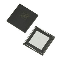
AS3991-BQFT austriamicrosystems, AS3991-BQFT Datasheet - Page 17

AS3991-BQFT
Manufacturer Part Number
AS3991-BQFT
Description
IC UHF RFID READER 64-QFN
Manufacturer
austriamicrosystems
Specifications of AS3991-BQFT
Rf Type
Read / Write
Frequency
840MHz ~ 960MHz
Features
ISO-18000-6
Package / Case
64-VFQFN, Exposed Pad
Lead Free Status / RoHS Status
Lead free / RoHS Compliant
Other names
AS3991-BQFT
AS3991-BQFTTR
AS3991-BQFTTR
AS3990/AS3991
Data Sheet - D e t a i l e d D e s c r i p t i o n
The digital modulation input in direct mode is IO3. RF field is set to high level if IO3 is high, and to low level if IO3 is
low. IO2 is used as RX enable. For correct operation, follow the instructions given below:
Modulator
For the modulation signal source, there are three possibilities:
The internal modulator is capable of DSB-ASK and PR-ASK modulation. Modulation shape is controlled with a double
D/A converter. The first one defines the upper (un-modulated) signal level while the second one generates the
modulation transient. The level defined by the first converter is filtered by capacitors on CD1 and CD2 pins to decrease
the noise level. The two levels are used as a reference for the shaping circuitry that transforms the digital modulation
signal to shaped analog modulation signal. Sinusoidal and linear shapes are available. The output of the shaping
circuit is interpolated and connected to the modulator input.
The output level and modulation shape properties are controlled by the ‘Modulator control register’ (15). The level of
the output signal is adjusted by option bits tx_lev<4:0>. Modulation depth for ASK is adjusted by mod_dep<5:0> bits.
Valid values for DSB-ASK are 01 to 3F. PR-ASK modulation is selected by pr-ask bit high. In case of PR-ASK, the
mod_dep<5:0> bits are used to adjust the delimiter/first zero timing. Linear modulation shape is selected by lin_mod
bit. The rate of the modulation transient is automatically adjusted to selected Tari and can be adjusted by
ask_rate<1:0> bits. For smoother transition of the modulation signal, an additional low pass filter can be used. The
Filter will be enabled by e_lpf bit. The adjustment step is 1.6%, 3F gives 100% ASK modulation depth.
PR-ASK modulation is selected by pr-ask bit high. In case of PR-ASK the mod_dep<5:0> bits are used to adjust the
delimiter/first zero timing in a range 9.6µs to 15.9µs. Linear modulation shape is selected by lin_mod bit. The rate of
the modulation transient is automatically adjusted to selected Tari and can be adjusted by ask_rate<1:0> bits. For
smoother transition of the modulation signal, additional low pas filter can be used by e_lpf bit.
In ASK modulation it is possible to adjust delimiter length by setting option bit ook_ask in the ‘Modulator control
register’ (15). In this case, ook_ask defines 100% ask modulation and the mod_dep<5:0> bits are used for delimiter
length setting similar to the PR-ASK mode.
Bits aux_mod and main_mod define whether the modulation signal will be connected to the auxiliary low power output
or to the main PA output. In case one of the outputs are enabled by the etxp<3:0> bits and appropriate aux_mod or
main_mod bit is low, the output is enabled but not modulated.
Amplifier
The following two outputs are available:
www.austriamicrosystems.com
Normal data mode – Internally coded and internally shaped.
Externally coded and internally shaped modulation enabled by entering direct mode. For more information on
entering and terminating the direct mode, refer to
Externally coded and externally shaped modulation is enabled by setting option bit e_amod in the ‘Modulator
control register’ (15) and entering direct mode. For more information on entering and terminating the direct mode,
refer to
should be 2.2V, amplitude 600mVp. It is also possible to use CD1 and CD2 pins as high and low reference for the
external modulation shape circuitry.
Low power high linear output (~0dBm) can be used for driving an external amplifier. This output uses RFOPX
and RFONX pins and it has nominal output impedance of 50Ω. It needs an external RF choke and de-coupling
capacitor for operation. It is also possible to use differential output for driving balanced loads. The output is
enabled by etx<1:0> bits in the ‘Regulator an IO control’ (0B) register
is also possible to adjust current capability of the output.
1. Configuration registers should be defined, starting from reg01
2. Direct command Enable RX (97) should be sent
3. Bit direct should be written to reg00
4. IO2 should be low during data transmission via IO3
5. IO2 should be changed to high level just before the reception is expected
6. IO3 should be maintained high during reception
Direct Mode on page
16. In this case, ADC and DAC pins are differential modulator input. The DC level
Revision 3.81
Direct Mode on page
(see Table
16.
24). With the help of these bits, it
17 - 51


