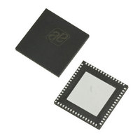
AS3991-BQFT austriamicrosystems, AS3991-BQFT Datasheet - Page 20

AS3991-BQFT
Manufacturer Part Number
AS3991-BQFT
Description
IC UHF RFID READER 64-QFN
Manufacturer
austriamicrosystems
Specifications of AS3991-BQFT
Rf Type
Read / Write
Frequency
840MHz ~ 960MHz
Features
ISO-18000-6
Package / Case
64-VFQFN, Exposed Pad
Lead Free Status / RoHS Status
Lead free / RoHS Compliant
Other names
AS3991-BQFT
AS3991-BQFTTR
AS3991-BQFTTR
AS3990/AS3991
Data Sheet - D e t a i l e d D e s c r i p t i o n
The second section comprises the framing logic for the protocols supported by the bit decoder section. In the framing
section, the serial bit stream data is formatted in bytes. The preamble, FrameSync, and CRC bytes are checked and
removed. The result is ‘clean’ data, which is sent to the 24-byte FIFO register where it can be read out by the host
system (MCU).
In the EPC Gen2 protocol, the decoder supports long RX preamble (TRext=1) for FM0, and all Miller coded signals and
short RX preamble (Trext=0) for Miller4 and Miller8 coded signals. In the EPC Gen2 protocol, the timing between
transponders response and the subsequent reader’s command is quite short. To relieve the host system (MCU) of
reading RN16 (or handle) out of the FIFO and then writing it back into the FIFO, there is a special register for storing
last received RN16 during the Query, QueryRep, QueryAdjust or RegRN commands. The last stored RN16 is
automatically used in ACK command.
The start of the receive operation (successfully received preamble) sets the flags in the ‘IRQ and status’ register. The
end of the receive operation is signalled to the host system (MCU) by sending an interrupt request (pin IRQ). If the
receive data packet is longer than 8 bytes, an interrupt is sent to the MCU when the 18
the data should be removed from the FIFO.
In case an error in data format or in CRC is detected, the external system is made aware of the error by an interrupt
request pulse. The nature of the interrupt request pulse is available in the ‘IRQ and status register’ (0C)
The receive part comprises two timers.
‘RX length register’ (1A, 1B) defines the number of bits that the receiver should receive. The number of bits is taken
into account only in case the value is different than 0 00, otherwise receiver stops on pause at the end of reception.
Since in noisy environment, the end of transponders transmission is not precisely defined using the RX length registers
improves the probability for successful receiving. For direct commands 98 to 9C, the RX length is internally set to 16 to
receive RN16. For direct command 9F, the RX length is internally set to 32 to receiveRN16 and CRC. For other
commands when the host system knows the expected RX length, it is recommended to write it in the RX length
register. The only case when RX length is not known in advance is reception of the PC+EPC.
AS3991 and above handle the afore mentioned issue by using special RX mode. The idea is that reader chip
generates an additional interrupt after two bytes (PC part of the PC+EPC field) are received. MCU reads out the two
bytes that define the length of the on going telegram and writes it in the RX length register.
To use IRQ after the two received bytes, the fifo_dir_irq2 bit in the reg1A should be set and non-zero length (typical
PC+EPC length) should be written in the 1B register before start of reception. The fifo_dir_irq2 performs the following
changes in the behavior of the logic:
www.austriamicrosystems.com
The RX wait time timer setting is controlled by the value in the ‘RX wait time’ (08)
defines the time after the end of transmit operation in which the receive decoders are not active (held in reset
state). This prevents any incorrect detection that could be caused as a result of transients that are caused by
transmit operation or transients that are caused by noise or interference. The value of the ‘RX wait time register’
defines this time with increments of 6.4µs. This register is preset at every write to the “Protocol control” register
(01) according to the minimum tag response time defined by default register definition.
The RX no response timer setting is controlled by the ‘RX no response wait time’ (07)
measures the time from the start of slot in the anti-collision sequence until the start of tag response. If there is no
tag response in the defined time, an interrupt request is sent and a flag is set in ‘IRQ status control’ register. This
enables the external controller to be aware of empty slots. The wait time is stored in the register with increments of
25.6µs. This register is automatically preset for every new protocol selection.
All received bytes are directly transferred to FIFO.
Normally the receiving data is pipelined, causing that the two CRC bytes are not seen in the FIFO. If dir_fifo=1,
then all bytes including CRC are seen in the FIFO.
Additional interrupt is generated after two bytes are received. In the IRQ status register, the ‘header/2byte’ (B3) bit
is set. If the reception is still in progress, IRQ status value is 48.
At this moment, the MCU needs to read out the first two bytes (PC part of the PC+EPC field) and set RX length
accordingly. The fifo_dir_irq2 bit should be maintained high.
At the end of reception, another IRQ is generated. Additional IRQ status bit ‘Irq_err3 – preamble/end’ (B1) is set.
IRQ status is 42 if the intermediate 2nd_byte interrupt was read out and cleared, or 4A if the reception was over
before the intermediate interrupt was read out and cleared.
Revision 3.81
th
(see Table
byte is received to signal that
(see Table
21). This timer
20). This timer
(see Table
20 - 51
25).


