Chameleon-AVR Nurve Networks, Chameleon-AVR Datasheet - Page 102
Chameleon-AVR
Manufacturer Part Number
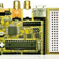
Chameleon-AVR
Description
MCU, MPU & DSP Development Tools AVR8 & PROPELLER DEV SYSTEM (SBC)
Manufacturer
Nurve Networks
Datasheet
1.CHAMELEON-AVR.pdf
(268 pages)
Specifications of Chameleon-AVR
Processor To Be Evaluated
AVR 328P
Data Bus Width
8 bit
Interface Type
USB, VGA, PS/2, I2C, ISP, SPI
Operating Supply Voltage
3.3 V, 5 V
Lead Free Status / RoHS Status
Lead free / RoHS Compliant


Moving on, the next area of interest is the “Flash” section of the tab. This is very important and what we will be using to
program the AVR chip. Make sure the second radio button “Input HEX File” is selected, then you must navigate on your
hard drive in your project directory to the .HEX file you wish programmed in each time. Now, this is an area that people
make a lot of mistakes, so please read the warning below very carefully.
Considering the warning, make sure that the input file is set correctly. To do this, navigate with the […] button to the right
of the control and locate your project directory for our work project named “\cham_avr_work_01\default” inside this
directory you will find the .HEX file that AVR Studio and GCC generated, select the file and the tool will have the proper
source data. Realize that every time you re-compile and build the project the .HEX file for the project is also updated,
thus, the programming tool always points to the latest and most updated .HEX file.
At this point, we still are not ready to program the unit, we need to set the “Fuses” and “Lockbits” tabs properly. So,
make sure your “Program” tab looks like the image shown in Figure 15.37 and then select the “Fuses” tab. You should
see something like that shown in Figure 15.38.
The “Fuses” tab controls a set of internal processor “fuses” that are no part of the FLASH or EEPROM memories.
Rather, the fuses control the “personality” of the chip in a number of areas. Thus, we must set these fuses every time we
program the processor, so that they are correct. Referring to Figure 15.38, you can see there are a lot of fuse settings and
a lot of cryptic labels on the left hand side. First, simply mimic what you see in the figure and set your fuses to exactly
these values. Be specially cognizant of the settings for:
WARNING!
The AVR ISP tool is completely separate from AVR Studio. In other words, when you
have a project opened in AVR Studio, it in no way communicates with the programming
tool. Thus, you can open up 100 different projects, but the programming tool will always
have the same settings which leads to confusion. This is a big problem since you might
be working on project_1, set the programming tool a certain way, then program the
chip, everything works fine. Then you work on project_2, set the programming tool
another way, everything works fine. Now, you reload project_1, open up the
programming tool, assume that it’s settings were saved with project_1, but in fact they
are whatever there were last which was project_2 ! Thus, you have a problem. So the
moral of the story is always check out the programming tool’s settings, especially the
“Main”, “Program”, “Fuses” and “Lockbits”.
Figure 15.38 – The AVR ISP MKII control panel’s “Fuses” tab.
© 2009 NURVE NETWORKS LLC “Exploring the Chameleon AVR 8-Bit”
102
Related parts for Chameleon-AVR
Image
Part Number
Description
Manufacturer
Datasheet
Request
R

Part Number:
Description:
MCU, MPU & DSP Development Tools PIC24 & PROPELLER DEV SYSTEM (SBC)
Manufacturer:
Nurve Networks
Datasheet:

Part Number:
Description:
MCU, MPU & DSP Development Tools AVR8 VIDEO GAME DEV SYSTEM (SBC)
Manufacturer:
Nurve Networks

Part Number:
Description:
MCU, MPU & DSP Development Tools PIC24 VIDEO GAME DEV SYSTEM (SBC)
Manufacturer:
Nurve Networks