Chameleon-AVR Nurve Networks, Chameleon-AVR Datasheet - Page 70
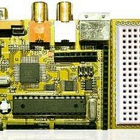
Chameleon-AVR
Manufacturer Part Number
Chameleon-AVR
Description
MCU, MPU & DSP Development Tools AVR8 & PROPELLER DEV SYSTEM (SBC)
Manufacturer
Nurve Networks
Datasheet
1.CHAMELEON-AVR.pdf
(268 pages)
Specifications of Chameleon-AVR
Processor To Be Evaluated
AVR 328P
Data Bus Width
8 bit
Interface Type
USB, VGA, PS/2, I2C, ISP, SPI
Operating Supply Voltage
3.3 V, 5 V
Lead Free Status / RoHS Status
Lead free / RoHS Compliant


© 2009 NURVE NETWORKS LLC “Exploring the Chameleon AVR 8-Bit”
Notice we are dealing in nanoseconds in the second example, this technique needs to run at a higher frequency to give
the “average” enough time to change at the highest frequency rate you want to synthesize in this method of D/A.
Figure 14.5 – A low pass “averaging” filter and the “stair step” results.
Now, the only mystery component to the D/A PWM converter is “averaging” of the signal. Well, fortunately for us, a low
pass filter as shown in Figure 14.5 acts as an averaging circuit, in fact, those of you with an EE background know that 1/S
is integral in the S-Domain and a low pass filter has a 1/S term it in. Intuitively it makes sense as well since a low pass
filter as shown in Figure 15.5(a) is really just a charging circuit and as we send these pulses to it, the circuit charges a bit,
then another pulse comes and it charges a bit more, when a pulse doesn’t come or the duty cycle is smaller then the RC
circuit discharges, so the PWM modulated pulse train gets turned into a signal by an “averaging” process and looks like
a stair step where you can see the averaging period superimposed on the signal. Figure 14.5(b) shows an example of
this. Here we see a PWM signal running at frequency f0, and a sine wave being synthesized at 1KHz before and after the
averaging circuit. We will get more into the programming of PWM when we discuss sound generation in the programming
section of the manual. But, for now realize that the low pass filter (LPF) that the Chameleon AVR uses on the audio
circuit acts as a LPF as well as an “averaging” circuit for PWM, so it has two uses – pretty cool.
14.1.3.1 Selecting the Filtering Frequency
Also, there are a couple of concerns with the actual values of the LPF, so that you don’t get too much noise. Noise is
going to come from the PWM frequency itself. For example, say you use a PWM frequency of 1MHz then your filter
obviously needs to cut this frequency out, but it also needs to cut in at the highest frequency you plan to synthesis, for
example, if you plan to have sounds all the way up to CD quality at 44KHz then you might set the 3dB point at 50KHz for
example.
Also, we are using an “passive” or “inactive” single pole filter. You might want a “sharper” response in a more high
end sound system like a 2 or 4 pole system. You can achieve this by daisy chaining our little LPFs together OR you can
use an “active filter” that consumes power based on a transistor or better yet simple Operational Amplifier (Op Amp)
like the LM 741. Or better yet pick an 8-pole switched capacitor filter by National, TI, or Linear Tech and the signal will hit
a “brick wall” at the cutoff ☺
But, for our purposes; games, simple music, audio warnings, sound effects, etc. a single pole passive filter will do fine, if
there is one thing I know, most people can’t tell the difference between 16-bit, 96 KHz sound and 8-bit, 11 KHz, so sound
generation can be a little rough!
14.1.3.2 PWM Setup Procedure
As mentioned, we will write some real code in the software section of this manual, but just to get you thinking about it, let’s
briefly digress a moment and work up an example with real numbers, so you can see this all in your head. Many of you
are already sound experts and half of us have written MOD players and done DOS games for years, so this is old news,
simple stuff, but a couple of you may never have played with sound, so this review can’t hurt.
70
Related parts for Chameleon-AVR
Image
Part Number
Description
Manufacturer
Datasheet
Request
R

Part Number:
Description:
MCU, MPU & DSP Development Tools PIC24 & PROPELLER DEV SYSTEM (SBC)
Manufacturer:
Nurve Networks
Datasheet:

Part Number:
Description:
MCU, MPU & DSP Development Tools AVR8 VIDEO GAME DEV SYSTEM (SBC)
Manufacturer:
Nurve Networks

Part Number:
Description:
MCU, MPU & DSP Development Tools PIC24 VIDEO GAME DEV SYSTEM (SBC)
Manufacturer:
Nurve Networks