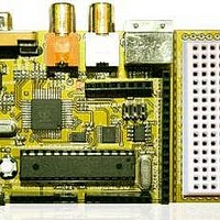
Chameleon-AVR Nurve Networks, Chameleon-AVR Datasheet - Page 20

Chameleon-AVR
Manufacturer Part Number
Chameleon-AVR
Description
MCU, MPU & DSP Development Tools AVR8 & PROPELLER DEV SYSTEM (SBC)
Manufacturer
Nurve Networks
Datasheet
1.CHAMELEON-AVR.pdf
(268 pages)
Specifications of Chameleon-AVR
Processor To Be Evaluated
AVR 328P
Data Bus Width
8 bit
Interface Type
USB, VGA, PS/2, I2C, ISP, SPI
Operating Supply Voltage
3.3 V, 5 V
Lead Free Status / RoHS Status
Lead free / RoHS Compliant
- Current page: 20 of 268
- Download datasheet (17Mb)
course, the AVR 328P allows re-writing to the FLASH as well, so unused portions of FLASH can be used for storage;
however, it’s not ideal to constantly re-write FLASH since there is a limit to the number of times it can be re-written;
100,000 give or take. Additionally, you can use the 1MByte SPI FLASH on the Chameleon as well for storage.
Note: The “P” suffix simply means “Pico Power” and has nothing to do with the chip operation or functionality. The Pico
power version is identical to the non-pico power for our purposes and I will use them interchangeably.
Figure 1.5 shows the AVR 328P architecture in block diagram form and Table 1.3 lists the pins and their function for the
AVR 328P.
Pin Group
Port B (PB7:PB0) - Port B is an 8-bit bi-directional I/O port with internal pull-up resistors (selected for each bit). The Port
B output buffers have symmetrical drive characteristics with both high sink and source capability. As inputs, Port B pins
that are externally pulled low will source current if the pull-up resistors are activated. The Port B pins are tri-stated when a
reset condition becomes active, even if the clock is not running. Port B also contains the SPI interface signals as well as
the clocking input pins.
Port C (PC6:PC0) - Port C serves as analog inputs to the Analog-to-digital Converter. Port C is an 7-bit bi-directional I/O
port with internal pull-up resistors (selected for each bit). The Port C output buffers have symmetrical drive characteristics
with both high sink and source capability. As inputs, Port C pins that are externally pulled low will source current if the pull-
up resistors are activated. The Port C pins are tri-stated when a reset condition becomes active, even if the clock is not
running. Note: even though Port C only has 7-pins bonded out on the chip, the port register is still 8-bits wide, but the 8
bit is simply ignored.
Port D (PD7:PD0) - Port D is an 8-bit bi-directional I/O port with internal pull-up resistors (selected for each bit). The Port
D output buffers have symmetrical drive characteristics with both high sink and source capability. As inputs, Port D pins
that are externally pulled low will source current if the pull-up resistors are activated. The Port D pins are tri-stated when a
reset condition becomes active, even if the clock is not running. Port D also contains the UART signals.
NOTE
NOTE
FLASH memories typically have a maximum number of times they can be written;
something in the range of 10,000 to 100,000. This doesn’t mean that at 10,001 or
100,001 the memory won’t work, it just means the erase cycles and write cycles may
take longer to get the memory to clear or write. And this then degrades further as the
write/erase cycles persist. Thus, if you were to code all day and re-write your FLASH
100x times a day, then at 100,000 re-write cycles, you would have 3-4 years before you
ever saw any problems. On the other hand, if you write code to use the FLASH as a
solid state disk and constantly re-write the memory 10,000x a run, you can see how
quickly you might degrade the memory. Thus, use the EEPROM for memory you need
to update and still be non-volatile and save the life of the FLASH.
Since the AVR 328P has so many internal peripherals and only a finite number of pins,
many functions are multiplexed on the I/O pins such as SPI, I2C, UARTs, A/D, D/A, etc.
Thus, when you enable one of the peripherals they will typically override the I/O
functionality and take on the special functions requested. However, when you don’t
enable any peripherals each I/O pin is a simple I/O pin as listed in Table 1.3.
Description
Table 1.2 - Differences between ATmega 48P, 88P, 168PP, and 328P.
Device
ATmega 48P
ATmega 88P
ATmega168P
ATmega328P 32 K Byte
Table 1.3 – The AVR 328P general pin descriptions.
Flash
4 K Byte
8 K Byte
16 K Byte
EEPROM
256 Bytes
512 Bytes
512 Bytes
1 K Byte
© 2009 NURVE NETWORKS LLC “Exploring the Chameleon AVR 8-Bit”
RAM
512 Bytes
1 K Byte
1 K Byte
2 K Byte
th
20
Related parts for Chameleon-AVR
Image
Part Number
Description
Manufacturer
Datasheet
Request
R

Part Number:
Description:
MCU, MPU & DSP Development Tools PIC24 & PROPELLER DEV SYSTEM (SBC)
Manufacturer:
Nurve Networks
Datasheet:

Part Number:
Description:
MCU, MPU & DSP Development Tools AVR8 VIDEO GAME DEV SYSTEM (SBC)
Manufacturer:
Nurve Networks

Part Number:
Description:
MCU, MPU & DSP Development Tools PIC24 VIDEO GAME DEV SYSTEM (SBC)
Manufacturer:
Nurve Networks


