Chameleon-AVR Nurve Networks, Chameleon-AVR Datasheet - Page 31
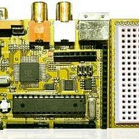
Chameleon-AVR
Manufacturer Part Number
Chameleon-AVR
Description
MCU, MPU & DSP Development Tools AVR8 & PROPELLER DEV SYSTEM (SBC)
Manufacturer
Nurve Networks
Datasheet
1.CHAMELEON-AVR.pdf
(268 pages)
Specifications of Chameleon-AVR
Processor To Be Evaluated
AVR 328P
Data Bus Width
8 bit
Interface Type
USB, VGA, PS/2, I2C, ISP, SPI
Operating Supply Voltage
3.3 V, 5 V
Lead Free Status / RoHS Status
Lead free / RoHS Compliant


Signal
MISO
MOSI
SCK
RESET
VTG
GND
The ISP protocol supports little more than reading and writing AVR (FLASH and EEPROM), resetting it, manipulating the
“fuse” register settings and so forth. Debugging is NOT supported. However, you can build a AVR ISP programmer fairly
easy and lots of schematics and designs are on internet that need only a RS-232 or parallel port. However, the Atmel
product is USB based for speed.
Figure 4.3 shows the actual circuitry for the ISP interface. As you can see its fairly straightforward. Nothing more than the
port header routed to the proper pins and a bypass cap on the power signals. Also, the ISP programmer pulls its power
from the Chameleon which is on the order of 50mA.
5.0 Serial USB UART Programming Port
The Propeller chip as well as the AVR can also be programmed via the serial USB UART. The Propeller uses serial to
communicate as default; however, the AVR uses serial only when there is a “bootloader” programmed into the AVR that
“listens” to the serial port and there is a protocol in place as well as tool on the other end that follow the protocol
agreement to re-program the FLASH. Therefore, the native method to re-program the Propeller is via the serial
connection, but the AVR is typically re-programmed via the USP port, thus the serial re-programming is a trick/hack that is
simply supported by a bootloader that supports it. With that in mind, the next section cover the USB UART design, but
before we take a look at that there is one sub-section of the design we need to look at and that’s the serial port “routing”
switch shown in Figure 5.1.
TIP
6-pin
1
4
3
5
2
6
The AVR ISP uses the primary SPI interface on the AVR, therefore, if you have anything
connected to the SPI pins on the interface headers you might need to remove it during
ISP programming, so you don’t have conflicts.
9
1
7
5
2
3,4,6,8,10
Figure 4.3 – The Chameleon ISP programming interface schematics.
10-pin
I/O
Input
Output
Output
Output
POWER
POWER
Table 4.1 – AVR ISP signals.
Description
Data from target AVR to AVR ISP.
Data from AVR ISP to target.
Serial clock from AVR ISP.
Reset from AVR ISP.
Power from target to power AVR ISP (< 50mA).
System ground.
© 2009 NURVE NETWORKS LLC “Exploring the Chameleon AVR 8-Bit”
31
Related parts for Chameleon-AVR
Image
Part Number
Description
Manufacturer
Datasheet
Request
R

Part Number:
Description:
MCU, MPU & DSP Development Tools PIC24 & PROPELLER DEV SYSTEM (SBC)
Manufacturer:
Nurve Networks
Datasheet:

Part Number:
Description:
MCU, MPU & DSP Development Tools AVR8 VIDEO GAME DEV SYSTEM (SBC)
Manufacturer:
Nurve Networks

Part Number:
Description:
MCU, MPU & DSP Development Tools PIC24 VIDEO GAME DEV SYSTEM (SBC)
Manufacturer:
Nurve Networks