Chameleon-PIC Nurve Networks, Chameleon-PIC Datasheet
Chameleon-PIC
Specifications of Chameleon-PIC


Related parts for Chameleon-PIC


Chameleon-PIC Summary of contents
Page 1
...
Page 2
... CHAMELEON™ PIC 16-Bit User Manual v1.0 “Exploring the CHAMELEON PIC 16-Bit – A Guide to Programming the CHAMELEON PIC 16-Bit System” Copyright © 2009 Nurve Networks LLC Author Joshua Hintze Andre’ LaMothe Editor/Technical Reviewer The “Collective” Printing 0001 ISBN Pending All rights reserved ...
Page 3
... Licensing, Terms & Conditions NURVE NETWORKS LLC, . END-USER LICENSE AGREEMENT FOR CHAMELEON PIC HARDWARE, SOFTWARE , EBOOKS, AND USER MANUALS YOU SHOULD CAREFULLY READ THE FOLLOWING TERMS AND CONDITIONS BEFORE USING THIS PRODUCT. IT CONTAINS SOFTWARE, THE USE OF WHICH IS LICENSED BY NURVE NETWORKS LLC, INC., TO ITS CUSTOMERS FOR THEIR USE ONLY AS SET FORTH BELOW. IF YOU DO NOT AGREE TO THE TERMS AND CONDITIONS OF THIS AGREEMENT, DO NOT USE THE SOFTWARE OR HARDWARE ...
Page 4
... The information herein will usually apply to newer versions but may not apply to older versions. Please contact Nurve Networks LLC for any questions you may have. Visit www.xgamestation.com & www.chameleon-dev.com for downloads, support and access to the Chameleon user community and more! For technical support, sales, general questions, share feedback, please contact Nurve Networks LLC at: support@nurve.net / nurve_help@yahoo.com © ...
Page 5
... CHAMELEON PIC 16-Bit” User Manual and Programming Guide LICENSING, TERMS & CONDITIONS ................................................................................................. 3 VERSION & SUPPORT/WEB SITE ...................................................................................................... 4 “EXPLORING THE CHAMELEON PIC 16-BIT” USER MANUAL AND PROGRAMMING GUIDE ..... 5 0.0 INTRODUCTION AND ORIGINS .................................................................................................. 11 1.0 ARCHITECTURAL OVERVIEW ................................................................................................... 13 1.1 Package Contents ............................................................................................................................................................................. 15 1.2 Chameleon PIC “Quick Start” Demo ............................................................................................................................................ 16 First Things First ...
Page 6
... INSTALLING THE TOOLCHAINS: MPLAB, TEXTPAD, AND PROPELLER IDE ..................... 79 15.1 MICROCHIP’S MPLAB IDE TOOLCHAIN OVERVIEW ............................................................. 79 15.1.1 Installing MPLAB IDE 8.xx (Optional) .................................................................................................................................... 81 15.1.2 Installing the PICkit2 Hardware and Software (Optional) ..................................................................................................... 85 © 2009 NURVE NETWORKS LLC “Exploring the Chameleon PIC 16-Bit” 6 ...
Page 7
... Installing Microchip’s MPLAB C compiler for PIC24 MCUs ................................................................................................ 89 15.1.4 Building a Project and Testing the Tool Chain ........................................................................................................................ 94 15.1.4.1 Loading the binary into the Chameleon PIC using the PICkit 2 ......................................................................................... 104 15.1.4.2 Enabling Compiler Optimizations ....................................................................................................................................... 107 15.1.4.2 Final Words on MPLAB Toolchain Installation ................................................................................................................. 108 15 ...
Page 8
... API Listing Reference .................................................................................................................................................................. 196 23.3 API Functional Declarations ....................................................................................................................................................... 196 24.0 KEYBOARD LIBRARY MODULE PRIMER ............................................................................. 198 24.1 Header File Contents Overview .................................................................................................................................................. 198 24.2 API Listing Reference .................................................................................................................................................................. 199 24.3 API Functional Declarations ....................................................................................................................................................... 200 © 2009 NURVE NETWORKS LLC “Exploring the Chameleon PIC 16-Bit” 8 ...
Page 9
... Adding PIC Support at the Client/Master Side ...................................................................................................................... 246 34.1 Advanced Concepts and Ideas .................................................................................................................................................... 248 35.1 Demo Coder Applications, Games, and Languages .................................................................................................................. 248 35.1.1 Chameleon BASIC by David Betz ......................................................................................................................................... 248 35.1.2 Crate-It Cook .............................................................................................................................................................. 249 © 2009 NURVE NETWORKS LLC “Exploring the Chameleon PIC 16-Bit” 9 ...
Page 10
... Epilog - From Intel 4004 to the Multiprocessing/Multicore Chameleon ......................................................................................... 249 APPENDIX A: SCHEMATICS .......................................................................................................... 250 APPENDIX B: MICROCHIP PIC24HJ PINOUT ............................................................................... 252 APPENDIX C – BOARD LAYOUT AND I/O HEADERS .................................................................. 253 APPENDIX D - USING THE PIC IN "STAND-ALONE" MODE. ....................................................... 254 APPENDIX E - USING THE PROPELLER IN "STAND-ALONE" MODE. ....................................... 254 APPENDIX F – PORTING HYDRA AND PARALLAX DEVELOPMENT BOARD APPLICATIONS TO THE CHAMELEON ...
Page 11
... I/O. The selection of the processors was difficult as it always is. We have to balance price, performance, user base, flexibility and a number of other factors. Additionally, since the Chameleon is a dual processor design, I had to think of a clean way to interface the processors such as shared memory, SPI, I use the Microchip PIC24HJ128GP502 processor for the Master and the Parallax Propeller chip for the Slave ...
Page 12
... Arduino software and tools on the Chameleons. Of course, I was using the new Atmel 328P in my designs and Arduino was still using the Atmel 168, but I hoped they would upgrade in time and they did! So now the Chameleons will run the Arduino tool chain and you can use Chameleons as supped up Arduinos. Of course, our boards are physically different and our headers are slightly different, but more or less with a little work any program designed for the Arduino can be ported to the Chameleon in a matter of minutes ...
Page 13
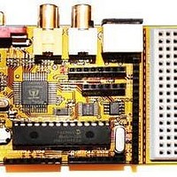
... Architectural Overview The Chameleon PIC 16-Bit or simply the “Chameleon PIC” is developed around the Microchip PIC 16-Bit 24HJ128GP502 28-Pin DIP. Figure 1.0 shows an image of the Chameleon PIC 16-Bit annotated. The Chameleon PIC has the following hardware features: 28-Pin DIP Package version of the PIC24HJ, runs at 40 MHz. ...
Page 14
... This is no problem for the chameleon! You would take you original program, compile it for the Chameleon, then add a few lines of code from our NTSC or VGA API that command the Propeller to draw text on the screen. Then you can print out your temperature information nicely on a little NTSC/VGA monitor. Moreover, you can write some simple GUI controls, so with the mouse or keyboard you could make command selections on the NTSC/VGA screen! Very slick! As another example, you can use the Chameleon’ ...
Page 15
... PICkit 2 ISP Programmer. The Chameleon will run off the USB cable, so you do not require a wall adapter for development. Also, the Chameleon PIC is pre-loaded with the microchip PIC24 bootloader, therefore, if you use the Chameleon in bootloader mode only you © 2009 NURVE NETWORKS LLC “Exploring the Chameleon PIC 16-Bit” ...
Page 16
... Appendices. First Things First... Before we plug the Chameleon in and test it, a couple things to pay attention to. First, the Chameleon can be powered by either adapter or draw power from the USB port connection. If you have adapter then you can use it for power. However, to “talk” to the Chameleon you are going to need a mini-B USB cable no matter what. Therefore, when we get to the power setup in Step 3, you can either plug in both the 9V adapter and the USB cable or just the USB cable ...
Page 17
... APIs to the Propeller are the same you get the exact same experience when you port an applications from the Chameleon AVR to PIC and vice versa. Of course, the PIC version is faster and has more memory – but, the AVR users like it that way – a challenge! Hit the Reset button over and over and the demo will reset and reload immediately, If the system ever locks up (rare, and always due to bad code), then simply hit Reset a few times or cycle the power ...
Page 18
... Figure 1.4 – The Microchip PIC24HJ packing for 28-Pin SDIP and SOIC packages. © 2009 NURVE NETWORKS LLC “Exploring the Chameleon PIC 16-Bit” 18 ...
Page 19
... Figure 1.5 – The Microchip PIC24HJ architecture block diagram. © 2009 NURVE NETWORKS LLC “Exploring the Chameleon PIC 16-Bit” 19 ...
Page 20
... FLASH memory of 128K Bytes, but a smaller 8K Byte SRAM which makes a lot of RAM intensive applications challenging; however, the Chameleon is designed for control applications and 8K of RAM should be more than enough for anything you need. For complete details on the processor, please review the datasheet located on the DVD-ROM here: DVD-ROM: \ cham_pic \ docs \ datasheets \ PIC24HJXXXXGPX06_08_10 ...
Page 21
... University, thus the moniker, and likewise Von Neumann was designed by mathematician John Von Neumann Von Neumann differs from Harvard in that Von Neumann uses a single memory for both data and program storage. © 2009 NURVE NETWORKS LLC “Exploring the Chameleon PIC 16-Bit” 21 ...
Page 22
... NURVE NETWORKS LLC “Exploring the Chameleon PIC 16-Bit” Figure 1.6 – FLASH and SRAM memory layouts. 22 ...
Page 23
... C compiler” sometimes also referred to as “pic30 compiler”. We will discuss the installation of the tool chain shortly, but keep in mind the separation. Additionally, we will be using straight “C” for coding. © 2009 NURVE NETWORKS LLC “Exploring the Chameleon PIC 16-Bit” Figure 1.7 – Microchip MPLAB in action. 23 ...
Page 24
... The downside with the simulator is that you will not be able to test peripherals like the UARTs, SPI, and the media processor capabilities provided by the Parallax Propeller. Figure 1.8 – The Parallax Propeller Chip block diagram. © 2009 NURVE NETWORKS LLC “Exploring the Chameleon PIC 16-Bit” 24 ...
Page 25
... P29 - I2C SDA connection to optional, external EEPROM. P30 - Serial Tx to host. P31 - Serial Rx from host. VDD --- 3.3 volt power (2.7 – 3.6 VDC) VSS --- Ground © 2009 NURVE NETWORKS LLC “Exploring the Chameleon PIC 16-Bit” Figure 1.9 – The Propeller pinouts. 25 ...
Page 26
... You simply write your code and run core. Then if that code crashes or is broken it does not affect the other cores at all! This is exactly what the Chameleon needs – a way to run multiple processes that each perform some kind of media task and then these processes wait for the master (the PIC) to send commands. Each core does not care what the neighboring cores are doing, only what it is doing. Luckily, if this all sounds like this is way too complicated, you don’ ...
Page 27
... Propeller couldn’t be programmed with a game, or other application and ignore the commands on the agreed to SPI interface pins. Therefore, the Chameleon can be used as a standalone PIC or Propeller controller if you wish. However, the point is to use them together than leverage their strong points; the PIC’s simple programming model, C ...
Page 28
... Part I - Hardware Design Primer In this section, we are going to cover every one of the Chameleon PIC’s hardware sub-sections, so you can get an idea of what’s going on and how the systems and signals are routed. Taken as a whole the Chameleon is rather complex, but as you will see, each individual sub-system is rather straightforward. Let’s begin with a bird’s eye view of the entire system schematic on the next page in landscape mode given in Figure 2 ...
Page 29
... Figure 2.0 (a) – The complete Chameleon PIC 16-bit schematic. © 2009 NURVE NETWORKS LLC “Exploring the Chameleon PIC 16-Bit” 29 ...
Page 30
... Figure 2.0(b) – The complete Chameleon PIC 16-bit PCB layout. © 2009 NURVE NETWORKS LLC “Exploring the Chameleon PIC 16-Bit” 30 ...
Page 31
... Figure 2.1 – The Chameleon PIC power supply design. The Chameleon PIC system has a duel 3.3V / 5.0V power supply system that is feed by a single 9V DC unregulated input from a wall adapter or feeds from the USB port header. The supplies design is shown in Figure 2.1 for reference. The supplies are straight forward, the only interesting thing is the coupling of the USB power and the regulated power at node 1 of the power switch SW1 ...
Page 32
... The PICkit 2 ISP programmer can control the RESETn line of the board and even supply 3.3V power if it detects the board is currently under powered. Explanations on how to use the PICkit 2 and the correct way to connect to the Chameleon PIC 16-bit are discussed in the programming section of this manual. © 2009 NURVE NETWORKS LLC “Exploring the Chameleon PIC 16-Bit” ...
Page 33
... Figure 4.2 shows the actual circuitry for the ISP interface. As you can see its fairly straightforward. Nothing more than the port header routed to the proper pins and a bypass cap on the power signals. © 2009 NURVE NETWORKS LLC “Exploring the Chameleon PIC 16-Bit” Table 4.1 – PIC ISP signals. ...
Page 34
... Typically, you will leave the switch in down (PIC mode) most of the time unless you are TIP constantly re-programming the driver on the Propeller chip. © 2009 NURVE NETWORKS LLC “Exploring the Chameleon PIC 16-Bit” Figure 5.1 – Serial port routing/selector switch. 34 ...
Page 35
... However, if you are going to use the Chameleon without a 9V power supply and power it from the USB port, I highly recommend you use a powered USB hub since the Chameleon will draw up to 200mA or more as it throttles its performance and powers up all its peripherals. ...
Page 36
... Take note of the SPI interface lines on the right, these are very important since they are used to communicate with the Propeller chip as well as the on board 1MB FLASH. © 2009 NURVE NETWORKS LLC “Exploring the Chameleon PIC 16-Bit” 36 ...
Page 37
... The Propeller can source up to 40mA per pin you tie 2 lines together and set them HIGH, you can source up to 80mA, more than enough for most applications. © 2009 NURVE NETWORKS LLC “Exploring the Chameleon PIC 16-Bit” Figure 8.1 – The Propeller Subsystem. ...
Page 38
... SPI selects to enable it. All the other SPI devices will be disabled and thus no bus contingency issues. 10.0 VGA Graphics Hardware In this chapter, we are going to take a look at the VGA hardware on the Chameleon PIC. The VGA hardware is very simple consisting of little more than (8) I/O lines, and (3) D/A converters based on resistors. The Propeller chip does all the work generating the VGA signal, but it’ ...
Page 39
... I checked on the Parallax Object Exchange. You can use any of these drivers with the Chameleon! You just need to modify the Propeller driver module, include the new VGA drivers, make connections to it via commands, and you are off and running. ...
Page 40
... Figure 10.1 – The Chameleon PIC VGA interface and support hardware. The VGA hardware for the Chameleon is very minimal since the Propeller chip is doing all the signal generation with direct control of the VGA signal via its built in VSU (video streaming unit). Of course, someone still has to write a driver for the VGA to work on the Propeller, but that’ ...
Page 41
... VGA mode (without any tricks). Not bad! For reference, the VGA connector has the following pin out shown in Table 10.3. The VGA port on the Chameleon PIC is a female HD15 (High Density) which is standard on the back of video card hardware. It will connect to any VGA monitor, but be careful when making connections, it’s a special “low profile” ...
Page 42
... LOW (but these can be inverted on most monitors) where a logic LOW is sync, and a logic HIGH is no sync. Now, let’s look more closely at the signal itself. © 2009 NURVE NETWORKS LLC “Exploring the Chameleon PIC 16-Bit” Table 10.3 - VGA female header pin out (HD15) ...
Page 43
... NURVE NETWORKS LLC “Exploring the Chameleon PIC 16-Bit” Figure 10.3 – The VGA timing specifications. ...
Page 44
... You might be wondering where the 25.175 MHz clock is generated on the Chameleon? NOTE Well, the Propeller chip is generating the signal and it has internal counters and PLLs that generate the 25.175 MHz signal for us. 10.3.1 VGA Horizontal Timing Referring to Figure 10.3(b), each of the 480 lines of video are composed of the following standard named regions: A (31.77 μ ...
Page 45
... I/O pins manually with pure software as well. Either way, let’s take a look at the mechanics of the signal. On the Chameleon PIC for example, there are 2-bits per channel, so the encoding of the VGA data byte is as simple as generating bytes in the format shown in Figure 10.4. ...
Page 46
... Programming for the Propeller Powered HYDRA” which you can find on Amazon.com, Parallax.com, and XGameStation.com. There is also some minimal © 2009 NURVE NETWORKS LLC “Exploring the Chameleon PIC 16-Bit” Table 11.1 – The Video Hardware. ...
Page 47
... Television signals and compatible displays are typically interlaced, and computer signals and compatible displays are typically progressive scan (non-interlaced). These two formats are incompatible with each other; one would need to be © 2009 NURVE NETWORKS LLC “Exploring the Chameleon PIC 16-Bit” 47 ...
Page 48
... A progressive, or non-interlaced, picture is painted on the screen by scanning all of the horizontal lines of the picture in one pass from the top to the bottom. This is illustrated in Figure 11.4. © 2009 NURVE NETWORKS LLC “Exploring the Chameleon PIC 16-Bit” Figure 11.3 - Interlaced scanning system. 48 ...
Page 49
... This compatibility is a major advantage for computer formats in that media, and content can be interchanged on a global basis. Table 11.2 lists some of the more popular formats along with comparisons of their specifications. © 2009 NURVE NETWORKS LLC “Exploring the Chameleon PIC 16-Bit” 49 ...
Page 50
... RCA jack. This is the same connector as that used for standard line level audio connections. S- video of course is slightly cleaner since the analog mixing of chroma and luma does NOT take place. A typical waveform of an all-white NTSC composite video signal is shown in Figure 11.5. © 2009 NURVE NETWORKS LLC “Exploring the Chameleon PIC 16-Bit” PAL HDTV/SDTV ...
Page 51
... Figure 11.6 (a) depicts yet another timing drawing the NTSC video signal, this time, more formally labeled at the RS-170A color standard created in the early 1950’s as the successor to the B/W only RS-170 standard created 1941. © 2009 NURVE NETWORKS LLC “Exploring the Chameleon PIC 16-Bit” Figure 11.5 - NTSC composite video waveform. ...
Page 52
... In general here are the steps to generating an NTSC signal. © 2009 NURVE NETWORKS LLC “Exploring the Chameleon PIC 16-Bit” 52 ...
Page 53
... Thus, most games systems don’t waste draw them, and simple increase the overscan regions good rule of thumb is that active video should be from 192-224 lines with equal amount of top and bottom overscan. © 2009 NURVE NETWORKS LLC “Exploring the Chameleon PIC 16-Bit” 53 ...
Page 54
... This is a 3.579594 MHz “tone” signal that the TV locks onto and uses as a phase reference for the remainder of the video line. The color of each pixel is determined by the © 2009 NURVE NETWORKS LLC “Exploring the Chameleon PIC 16-Bit” 54 ...
Page 55
... However, give everything a try and see what you get. 11.2.8 NTSC Signal References Here are a number of web sites and documents to help you understand the NTSC / PAL video formats: © 2009 NURVE NETWORKS LLC “Exploring the Chameleon PIC 16-Bit” 188. 55 ...
Page 56
... I/O pins and write our own driver. Or use one of the mouse/keyboard drivers already written for the Propeller which is the tactic we use for the Chameleon. More or less every single device interfaced uses a standard pre-written driver and all make calls to it from the PIC chip. But, it’s nice to know how these things work, so let’ ...
Page 57
... F0,1B ENTER T 2C F0, F0, F0, F0, F0, F0, F0,1A © 2009 NURVE NETWORKS LLC “Exploring the Chameleon PIC 16-Bit” . Description Keyboard clock signal, open collector. Keyboard data signal, open collector. Table 12.2 – Default scan codes. KEY MAKE BREAK 9 46 F0, F0, F0, FO, ...
Page 58
... DIN’s pin out is shown in Figure 12.2 (referenced looking at the computer’s female side where you plug the keyboard into, notice the staggering of the pin numbering). Figure 12.2 - Female PS/2 6-Pin Mini Din Connector at Chameleon PIC socket. Table 12.3 lists the signals for reference, the descriptions of the signals are as follows: DATA Bi-directional and used to send and receive data ...
Page 59
... Then the keyboard will actually do the clocking while the host pulls on the data line at the appropriate times. The sequence is as follows: © 2009 NURVE NETWORKS LLC “Exploring the Chameleon PIC 16-Bit” Figure 12.3 – Keyboard Serial Data Packet. ...
Page 60
... Typematic Rate/Delay Option Byte |7|6|5|4|3|2|1| |-+-+-+-+---- typematic rate indicator (see INT 16, `-------- A in period formula (see below `------------ B is period formula (see below) © 2009 NURVE NETWORKS LLC “Exploring the Chameleon PIC 16-Bit” Table 12.4 – Keyboard Commands. (0=off, 1=on) (0=off, 1=on) (0=off, 1=on) ...
Page 61
... Again, we will cover real programming examples in the Programming Manual, but let’s just review the technical details briefly to get acquainted with the commands and data. © 2009 NURVE NETWORKS LLC “Exploring the Chameleon PIC 16-Bit” 61 ...
Page 62
... Mouse Data Packets The PS/2 mouse sends the movement information to the host which includes the position counters, button state, overflow flags and sign bits in the format show in Table 12.6. © 2009 NURVE NETWORKS LLC “Exploring the Chameleon PIC 16-Bit” Actual Movement Reported ...
Page 63
... Reporting Disabled". This means the mouse will not issue any movement data packets until it receives the "Enable Data Reporting" command. The various modes of operation for the mouse are: © 2009 NURVE NETWORKS LLC “Exploring the Chameleon PIC 16-Bit” Table 12.6 – Mouse data packet format. ...
Page 64
... After receiving the sample rate, the mouse again responds with "acknowledge" ($FA) and resets its movement counters. Most mice accept sample rates of 10, 20, 40, 60, 80, 100 and 200 samples/sec. © 2009 NURVE NETWORKS LLC “Exploring the Chameleon PIC 16-Bit” 64 ...
Page 65
... If the mouse is in Stream mode, the host should disable data reporting (command $F5) NOTE before sending any other commands. This way, the mouse won’t keep trying to send packets back while the host is trying to communicate with the mouse. © 2009 NURVE NETWORKS LLC “Exploring the Chameleon PIC 16-Bit” Bit 6 Bit 5 Bit 4 ...
Page 66
... That’s it! Of course, this is only for your edification, the Propeller driver does all this for you, so all you have send a simple command from the PIC to the Propeller to read the keyboard or mouse. © 2009 NURVE NETWORKS LLC “Exploring the Chameleon PIC 16-Bit” 66 ...
Page 67
... Propeller chip has its own 8-bit local I/O port located right under the composite video and PS/2 ports. The other headers surrounding the Chameleon PCB interface mostly to the PIC chip. Let’s take a look at the PCB for a moment for reference as shown in Figure 13.1. ...
Page 68
... Also, the pins on the headers obviously connect to multifunction pins such as the serial UARTS, SPI, and so forth. In the case of the Chameleon PIC most of these pins are remapable to any peripheral. Table 13.1 below maps the header pin names to the physical pin names and numbers for your convenience. ...
Page 69
... The Propeller does have counters on board and can generate PWM signals, thus the audio drivers typically leverage these hardware elements. Thus, for most audio applications that connect to a Propeller chip all you need is a typical PWM “integrator” or “low pass” filter. The Chameleon employs such a hardware design as shown in Figure 14.1. ...
Page 70
... Also, note that at DC, frequency f=0, the right hand term in the denominator sum (1 + 2*PI*0*RC thus the gain is 1/1 or 1.0 which is exactly what it should be! Cool huh! © 2009 NURVE NETWORKS LLC “Exploring the Chameleon PIC 16-Bit” Gain ...
Page 71
... PCM is a viable option for the Chameleon PIC, but there is so little FLASH memory (relatively speaking) you would have to stream off and external SD © 2009 NURVE NETWORKS LLC “Exploring the Chameleon PIC 16-Bit” ...
Page 72
... use the Chameleon PIC’s internal timers we can do this (more on this later can write a software loop to do it. For example, if you wanted to hear a 500KHz, 1KHz, and 2KHz signal you just write a software loop that toggles the output AUDIO_MONO at that rate and you will hear the sound on the attached output device. Figure 14.3 shows this graphically. Now, there are a couple problems with this ...
Page 73
... Figure 14.4(b) there are 10 total cycles and them we have 50% duty cycles for a total analog voltage per 10 clocks of: Average Signal @ 20% duty cycle = (5V)* (50%)*[ (100 ns) / (1000 0.5V. © 2009 NURVE NETWORKS LLC “Exploring the Chameleon PIC 16-Bit” Figure 14.4 - Duty cycle modes. 73 ...
Page 74
... We will get more into the programming of PWM when we discuss sound generation in the programming section of the manual. But, for now realize that the low pass filter (LPF) that the Chameleon PIC uses on the audio circuit acts as a LPF as well as an “averaging” circuit for PWM has two uses – pretty cool. ...
Page 75
... First, let’s look at the maximum signal frequency, if you want to play back all 256 sine samples then the maximum “signal” frequency is always: © 2009 NURVE NETWORKS LLC “Exploring the Chameleon PIC 16-Bit” 75 ...
Page 76
... OR just using the upper 8-bits at the index into our 256 element sine table (the latter is preferred). Then we simply need the magic number © 2009 NURVE NETWORKS LLC “Exploring the Chameleon PIC 16-Bit” | ...
Page 77
... PHASE_INC = 65536 * 2550 / 256,000 = 652.8 Now, this is a decimal number which will be truncated during the fixed point math to 652, but this is fine, that’s only an error or: © 2009 NURVE NETWORKS LLC “Exploring the Chameleon PIC 16-Bit” PHASE_INC PHASE_ACC PHASE_ACC (upper 8-bits) ...
Page 78
... In conclusion, that’s a taste of what goes into generating sounds on the Propeller chip. Then there is the whole other process of creating a sound engine on top of these techniques to play “music” such as MIDI or MOD. © 2009 NURVE NETWORKS LLC “Exploring the Chameleon PIC 16-Bit” PHASE_INC ...
Page 79
... PIC24 C compiler alone. However, I still recommend you skim the discussion of MPLAB since it’s a much more powerful tool than the command line tools. Additionally, the Chameleon has a Parallax Propeller chip on it have to install that tool as well, so there is a lot to do. We are going to show the installations of the tool in the following order: ...
Page 80
... MPLAB IDE 8.xx specifically can update any drivers needed for the tool. One thing you may notice is that the PICkit 2 hardware contains a female header and there are no male headers on the Chameleon PIC. We decided to keep only female headers on the board and you use a 6-pin right angle male connector to attach the PICkit 2 to the Chameleon. This will be explained with pictures shortly. ...
Page 81
... At this point, please launch the MPLAB IDE installation program. You should see the initial splash screen as show in Figure 15.2. Figure 15.2 – Initial splash screen for MPALB IDE 8.xx installer. © 2009 NURVE NETWORKS LLC “Exploring the Chameleon PIC 16-Bit” 81 ...
Page 82
... By choosing Custom we will get more of a “bare bones” installation. Press <Next> to continue to the next screen where we will choose our installation folder. © 2009 NURVE NETWORKS LLC “Exploring the Chameleon PIC 16-Bit” Figure 15.3 – MPLAB IDE License Agreement. ...
Page 83
... Device Support->16 bit MCUs) and (Microchip Applications->PICkit 2) everything else can be selected if you are going to use MPLAB for other projects than just the Chameleon PIC or if you have different programmers like the ICD2. Press <Next> to review all our settings before final install. ...
Page 84
... You will now see a progress bar, as shown in Figure 15.8, that gives us an indication of how much copying is left until our install is complete. If something is wrong you may stop it by pressing the Cancel button. Otherwise, let it finish. © 2009 NURVE NETWORKS LLC “Exploring the Chameleon PIC 16-Bit” Figure 15.8 – Installation progress bar. ...
Page 85
... If you opt for installing the PICkit 2 programming tool then the first step is to launch the installation executable found at the following location: DVD-ROM:\ CHAM_PIC \ TOOLS \ PIC \ PICkit 2 v2.61.00 Setup A \ setup.exe After the installation wizard begins you will see a dialog as shown in Figure 15.10 © 2009 NURVE NETWORKS LLC “Exploring the Chameleon PIC 16-Bit” 85 ...
Page 86
... When you have chosen your install location click <Next> to confirm the installation. © 2009 NURVE NETWORKS LLC “Exploring the Chameleon PIC 16-Bit” Figure 15.10 – PICkit 2 welcome screen. ...
Page 87
... The final step is to agree to the license agreement as shown in Figure 15.13. Click the “I Agree” radio button and simply press <Next> to being the coping process. © 2009 NURVE NETWORKS LLC “Exploring the Chameleon PIC 16-Bit” Figure 15.12 – Confirm PICkit 2 installation. ...
Page 88
... USB port. After the device has been enumerated you may launch the programmer tool by clicking on the new PICkit 2 icon located on your desktop. © 2009 NURVE NETWORKS LLC “Exploring the Chameleon PIC 16-Bit” Figure 15.15 – Installation complete. ...
Page 89
... Installing Microchip’s MPLAB C compiler for PIC24 MCUs The next component of the Chameleon PIC toolchain is Microchip’s C compiler for PIC24 processors, also known as the C30 compiler. This compiler is required for both the MPLAB installation and the serial bootloader option. We will be installing the student edition which has 60 days unlimited “ ...
Page 90
... C compiler, in which case I would suggest just writing the high performance portions in assembly. Figure 15.18 shows the conditions. Click <Next> to continue to the license agreement. © 2009 NURVE NETWORKS LLC “Exploring the Chameleon PIC 16-Bit” Figure 15.18 – Student edition limitations. ...
Page 91
... Simply press <Next> to continue, otherwise click the <Browse> button as shown in Figure 15.20 and select an appropriate install location. © 2009 NURVE NETWORKS LLC “Exploring the Chameleon PIC 16-Bit” Figure 15.20 – Installation location selection. ...
Page 92
... If you are sharing a computer with another user who might also want to use MPLAB then select “Install for all users” option (requires Administrator privileges), as shown in Figure 15.22. Otherwise, if you plan on working on the Chameleon PIC alone select “Install for current user only”. You can also choose to add a desktop icon for the C compiler documentation, by selecting the “ ...
Page 93
... PATH environment variable, see Figure 15.25. By saying yes you can run the command line tools from a command prompt without specifying the full path to the tools. This is required for the serial bootloader and TextPad installation to work properly, press <Yes> to allow it. © 2009 NURVE NETWORKS LLC “Exploring the Chameleon PIC 16-Bit” 93 ...
Page 94
... Release the processor from reset and verify operation. Before we go over the actual steps of creating a demo project we first need to copy all of the demo files and Chameleon PIC API libraries from the DVD-ROM to your local hard drive. Do this by opening up Windows Explorer and either copy or drag the entire source folder from the DVD-ROM to your hard drive ...
Page 95
... Now we need to create a blank project for the PIC24HJ128GP502 this, launch the Project Wizard by clicking on the menu item <ProjectProject Wizard> as shown in Figure 15.27. © 2009 NURVE NETWORKS LLC “Exploring the Chameleon PIC 16-Bit” Figure 15.27 – Selecting the project wizard. ...
Page 96
... Figure 15.29 shows the device selection dialog with a single drop down list to select your PIC processor. Click on the down arrow and choose “PIC24HJ128GP502”. Then click <Next> to advance to the language toolsuite. © 2009 NURVE NETWORKS LLC “Exploring the Chameleon PIC 16-Bit” Figure 15.29 – Device selection dialog. ...
Page 97
... MPLAB is smart enough to compile files from outside its directory. For now just choose a shallow location meaning don’t use a lot of spaces, strange symbols, or many sub-directories down for your project file © 2009 NURVE NETWORKS LLC “Exploring the Chameleon PIC 16-Bit” Figure 15.30 – Select a programming tool. ...
Page 98
... Do NOT add any files and click the <Next> button to go onto the summary window. © 2009 NURVE NETWORKS LLC “Exploring the Chameleon PIC 16-Bit” Figure 15.33 – Add files dialog. ...
Page 99
... Figure 15.34 – Final summary before project is created. Figure 15.34 shows the summary of your project parameters. If they look correct click <Finish> to exit the Project Wizard and your project will be created on disk. © 2009 NURVE NETWORKS LLC “Exploring the Chameleon PIC 16-Bit” Figure 15.35 – Empty demo project. 99 ...
Page 100
... IDE mode there may be others. For example when programming with the PICkit 2 there will be a tab for diagnostic messages from the PICkit 2 hardware displayed in the PICkit 2 tab on the Output window. © 2009 NURVE NETWORKS LLC “Exploring the Chameleon PIC 16-Bit” 100 ...
Page 101
... Files to Project…> menu item as shown in Figure 15.37. Go ahead and click on the “Add Files to Project” menu item as shown above. © 2009 NURVE NETWORKS LLC “Exploring the Chameleon PIC 16-Bit” Figure 15.38 – Adding source files to project. ...
Page 102
... We want to change this so we can select header files as well. Do this now by changing the drop down box of “Files of type” to “All Source and Header Files”. Now navigate to the Sources\ folder where you copied the Chameleon PIC DVD contents onto your hard drive. Add the following files: Drivers • ...
Page 103
... When you have completed adding the source, header, assembly, and linker script files to the project, your Project File Tree should resemble Figure 15.40. Now that the files are prepared we will build the project. © 2009 NURVE NETWORKS LLC “Exploring the Chameleon PIC 16-Bit” Figure 15.40 – All files added to the project. ...
Page 104
... If you purchased or already own the PICkit 2 hardware programmer you will use it now to load the binary hex file into the Chameleon PIC 16-Bit. If you own a different programmer such as the MPLAB ICD 2 or the new MPLAB ICD 3 the steps are very similar, however consult your user manual for proper directions. ...
Page 105
... Propeller port) PIC24 programming header. When you insert the PICkit 2 into the Chameleon PIC the PICkit 2 will not lay flush on the board, instead it will be propped angle, this is fine. Make sure the white arrow is facing away from the Propeller chip and is closer to the experimenter board region as shown in Figure 15 ...
Page 106
... Bring target MCLR to GND (place device in reset). 9. Re-establish PICkit 2 connection. Now that the programmer is attached to the Chameleon PIC we can tell the PICkit 2 device programmer to flash the binary file into the PIC24 processor this press the far left toolbar button “Program the target device” (1) as shown in Figure 15.45. This will begin loading the firmware into the Chameleon PIC and you may watch the progress through the PICkit 2 tab on the output window. After it’ ...
Page 107
... The final step is to release the Chameleon PIC from reset (which will also release the Propeller as well since the resets are the same). You can do this by either unplugging the PICkit 2 programmer or more easily press the “Bring target MCLR to VDD” (7) toolbar button. Now plug your Chameleon PIC into your NTSC television and VGA monitor and verify your screen looks similar to Figure 15.46 Figure 15.46 – ...
Page 108
... Files” folder of the same project, then “Build All” from the Main Menu’s “Build” menu then using the PICkit 2 programmer toolbar “Program” the Chameleon PIC with the new binary. That’s it! © ...
Page 109
... As you can see, the serial bootloader setup is a little bit easier than the MPLAB toolchain setup. In also requires less hardware. In fact the only required hardware is the PC and a USB cable which can also be used to power the Chameleon PIC. In this setup we have elected to use TextPad as our text editor, although any text editor could be used. TextPad also contains the ability to call command line console “ ...
Page 110
... FlashProg the exact part number of the PIC so that it knows which commands need to be sent to erase and load the flash correctly. Located on the Chameleon PIC (at least when it was originally shipped small section of code that acts as a bootloader. It operates by first configuring the serial port for 115200 baud rate and then begins listening for serial communication ...
Page 111
... By adding on the $File parameter this causes TextPad to take the current file name that you are editing in TextPad and to send that as a argument to our batch file. The second argument COMX (in my case COM7) is the communications port that the Chameleon is connected to. This can be found under the Device Manager in Windows and we will show you how to find it explicitly in Section 15.2.3 below. ...
Page 112
... README.txt – Thorough explanation of the files contained in the folder • bootloader.hex – The actual bootloader that can be reload onto the Chameleon PIC using a tool like the PICkit 2. • bootable_p24HJ128GP502.gld – Linker command script that reserves a region of free memory for the bootloader so that new compiled programs do not overwrite the bootloader. • ...
Page 113
... DVD-ROM:\ CHAM_PIC \ TOOLS \ DRIVERS \ USBDriverInstallerV2.04.16.exe After you have installed the driver, then each time you plug a Chameleon PIC into the PC via the USB port, the FTDI chip will assign a NEW COM port, you need to determine what COM port it attached itself to. Goto Windows Start menu on and select < ...
Page 114
... Chameleon PIC 16-bit ←-----Mini USB cable----------→PC Running Terminal Program (eg. PuTTY) The PC can talk to either the Propeller chip onboard the Chameleon via the USB port OR the standard serial port on the PIC chip, this is accomplished via a mechanical switch at the bottom of the board shown in Figure 15.53 below. ...
Page 115
... USB serial port. There are many serial terminal programs available (HyperTerminal for example), but we want you to use one that is very SIMPLE to setup and that works well with the Chameleon PIC, we are going to use “PuTTY”. From the DVD-ROM, install this program: DVD-ROM:\ CHAM_PIC \ TOOLS \ COMMUNICATIONS \ putty_install.exe It is called “ ...
Page 116
... Figure 15.54 - PuTTY Setup for serial communications with Chameleon PIC, 115200 baud, N81. Click on <Serial> for the connection type as shown in the top right, then click “Serial” on the bottom of the Category tree panel on the left and make sure the settings listed below and shown in Figure 15.55. ...
Page 117
... Figure 15.55 - PuTTY Setup for serial communications with Chameleon PIC, 115200 baud, N81, continued. To launch the terminal program, you would press <Open> which opens a new terminal window. This is where you would type on the PC keyboard to communicate with the Chameleon PIC and run the demos or do serial terminal experiments. 15.2.3.1 Running the Bootloader Tool We are all ready to go, let’ ...
Page 118
... Total program memory used (bytes): Data Memory [Origin = 0x800, Length = 0x2000] section address ------- ------- .nbss 0x800 .ndata 0x90c © 2009 NURVE NETWORKS LLC “Exploring the Chameleon PIC 16-Bit” length (PC units) length (bytes) (dec) ----------------- -------------------- 0x3392 0x4d5b (19803) 0x26 0x39 (57) 0x104 0x186 ...
Page 119
... But, if you do have the programmer or something else supported by MPLAB then you probably should work in the more robust MPALB since it allows debugging, simulation, etc. But, it’ you – just have fun! © 2009 NURVE NETWORKS LLC “Exploring the Chameleon PIC 16-Bit” 0 0x6 ...
Page 120
... Chameleon PIC (and AVR) uses a Propeller chip as the media processor, thus to program the Propeller chip’s EEPROM on the Chameleon with code we need to use this tool. The Propeller is a 32-bit processor and you program BASIC like language called SPIN, or you can program in Assembly language. The Propeller IDE supports both seamlessly. The assembly language is very nice, but SPIN takes a bit to get used to as does the editor which uses indentation like Python for block level ...
Page 121
... Step 3: VERY IMPORTANT! The Propeller tool IDE communicates to the Chameleon PIC using a USB cable and driver, this USB driver must be installed. The next dialog shown below in Figure 15.58 should have the “Automatically Install/Update driver” selected, so the driver is installed. Check this box and click <NEXT>. ...
Page 122
... Step 6: Click <OK> and the final installation should take place, you will see a dialog like that shown in Figure 15.61 below, click <FINISH> and this should complete the installation of the Propeller Tool IDE and the associated USB drivers it needs. Figure 15.61 – The final Propeller tool installation dialog. © 2009 NURVE NETWORKS LLC “Exploring the Chameleon PIC 16-Bit” 122 ...
Page 123
... PC recognizes the Chameleon and installs a virtual USB COM port. When you connected your test Chameleon PIC to the PC via the USB cable and powered the Chameleon up, the FTDI drivers on the PC should have detected a NEW USB port and assigned a COM port to it, you can find the COM port # in the system devices menu. You will need this later for the serial communications test, however, the Propeller tool will autoscan all COM ports until it finds the Propeller chip connected to one ...
Page 124
... Figure 15.63 – Loading the Propeller firmware into the tool. Once the source code is loaded into the tool, you simply have to download it into the Chameleon PIC. Make sure that you have the USB cable plugged into the Chameleon, power is ON, and the serial selection switch is in the UP position. ...
Page 125
... Once the firmware is downloaded into the Propeller chip on the Chameleon board it will immediately start generating NTSC and VGA video. If you hit RESET on the Chameleon, you will see the images shown in Figure 15.65 on the NTSC and VGA monitors respectively. © 2009 NURVE NETWORKS LLC “Exploring the Chameleon PIC 16-Bit” ...
Page 126
... Propeller chip is functioning correctly as well as to verify the LED is good. Finally, you will HEAR the Chameleon make sounds as it boots up, a series of tones that play musical notes when you hit RESET. Make sure to have the audio port plugged into your NTSC TV as well. ...
Page 127
... Chameleon Inter-Processor Architecture Overview In this section, we are going to go into a bit of detail in relation to the software engineering techniques that the Chameleon’s duel processor architecture is based on. This section isn’t necessary to use the Chameleon, but it’s necessary to understand the design more completely. ...
Page 128
... KEY_CMD_RESET = 16 KEY_CMD_GOTKEY = 17 KEY_CMD_KEY = 18 KEY_CMD_KEYSTATE = 19 KEY_CMD_START = 20 © 2009 NURVE NETWORKS LLC “Exploring the Chameleon PIC 16-Bit” Propeller IO Port Pins Used 12, 13, 14 (video LSB to MSB) 16(V),17(H),18(B1),19(B0),20(G1),21(G0),22(R1),23(R0) 26 (data), 27 (clock) 10 (PWM or pure signal) 30 (TX), 31 (RX) 128 ...
Page 129
... GFX_CMD_NULL: ' GFX GPU TILE ENGINE COMMANDS ///////////////////////////////////////////////////////////////////////////////////////// © 2009 NURVE NETWORKS LLC “Exploring the Chameleon PIC 16-Bit” ' low byte of 16-bit data & $FF) ' high byte of 16-bit data 0.. ...
Page 130
... In the sections below we will cover the exact drivers used, but the point is, they were chosen more or less for ease of use and user base. © 2009 NURVE NETWORKS LLC “Exploring the Chameleon PIC 16-Bit” 130 ...
Page 131
... Command Processing Loop – As SPI commands are sent over the SPI channel, the virtual SPI driver listens and if it detects traffic, it then processes the bytes and places them into a globally shared memory buffer. The MCP is sitting a © 2009 NURVE NETWORKS LLC “Exploring the Chameleon PIC 16-Bit” 131 ...
Page 132
... Also, there is a return value another 4-byte float, thus we need to “pack” the parameters up into a single record and pass it along and then wait for a single float (4-byte result). © 2009 NURVE NETWORKS LLC “Exploring the Chameleon PIC 16-Bit” 132 ...
Page 133
... But, let’s keep exploring the general idea of RPCs and some strategies that might help you later as you update/modify the default drivers shipped with the Chameleon. 16.3.1 ASCII or Binary Encoded RPCs When designing an RPC system you can make it really complex or really simple. The main idea is that you want to be able to call functions in another process, processor, machine. Decisions have to be made about the “ ...
Page 134
... RPC to perform calculations on. The database never changes need to keep sending it over and over, once it’s in the servers memory space, you can save the bandwidth. 16.3.3 Our Simplified RPC Strategy Considering all these interesting methods, the method used for the Chameleon is a 3-byte binary encoded SPI packets with the following format: [command8, data_low8, data_high8] Where command8 is an 8-bit command code, data_low8 and data_high8 are the operands for the command. Thus, each SPI packet is rather small and can’ ...
Page 135
... In the future, you might want to use other objects or improve these for more specific needs. In any event, referring to Figure 16.5. The objects used are shown in Table 16.2. Table 16.2 - Objects used for the Chameleon default MCP drivers. Function MCP (master control program) ...
Page 136
... NTSC terminal that might work better on some LCDs. You can drop down you have trouble with the default2 driver. Note 3: The Chameleon only has one PS/2 port, so only one driver; keyboard or mouse can be active at once. However, the default MCP driver can “hot” swap the drivers, so you can unplug the keyboard/mouse in real-time and with software “ ...
Page 137
... Chameleon PIC API Overview In this section of the manual we are going to discuss the Chameleon PIC API and its related components. First and foremost, I want to make it clear that the API we have developed means complete, the best, the fastest, etc. It’s just a set of source files and functions that get you started developing applications. Moreover, the whole idea of the Chameleon is to leverage the functionality of the drivers running on the Propeller chip. The PIC side API is nothing more than “ ...
Page 138
... In the section below we will briefly cover each one of these libraries and the functions within them. Before, we get started let’s take a look at the “big picture” illustrating all the components of the Chameleon PIC development suite of software and tools. Figure 17.1 shows a system level architecture diagram of all the pieces involved. ...
Page 139
... The answer is yes. However, you would have to go into the source files where printf(…) is located and modify “something” intelligent on the Chameleon PIC such as print to the UART the NTSC/VGA screen. But, you get the idea. Don’t use standard C functions that make no sense on an embedded system. ...
Page 140
... With that in mind, there are a number of .C and .H files that make each up class of library functionality for the Chameleon API. At this point, we are going to drill down and list each of the files with a short description. Then we are going to discuss the key data structures and header files for each library module, list the functions one by one with examples. © ...
Page 141
... The “System” library module consists of a single C source file and its header. The “System” modules must be included in every Chameleon PIC program since its contains some top level #defines, types, and other pertinent elements that other API modules depend on. In addition to the important #defines it also includes the function that configures the onboard PLL allowing us to switch from an internal ~7MHz RC clock to a full 40 MHz clock rate ...
Page 142
... Lastly, so that the user can change the system frequency if he wishes during run-time, there is a variable shadow of the MAX_FCY_RATE constant that is loaded with said constant during startup. Thus, the variable is used in the Chameleon PIC library for calculations. This gives it timing information and as noted the ability to be changed during run-time. ...
Page 143
... The “UART and RS-232” communications module supports basic transmission and reception of bytes to and from the Chameleon PIC serial port. The PIC24HJ has two very advanced UARTs (Universal Asynchronous Serial Receiver and Transmitters connected directly to the TX/RX pins of the USB FTDI chip which allows serial communication via the USB port ...
Page 144
... C putchar(…) and getchar(…) called UART_putchar(…) and UART_getchar(…) these functions directly access the transmit and receive buffers for you. Thus, from a software perspective all the work of polling the transmission and © 2009 NURVE NETWORKS LLC “Exploring the Chameleon PIC 16-Bit” 144 ...
Page 145
... Fortunately, the codes that we will use most often seem to work among most terminal emulators. An example VT100 command to clear the terminal screen is: <ESC>[2J © 2009 NURVE NETWORKS LLC “Exploring the Chameleon PIC 16-Bit” Figure 18.2 – DEC VT100 Terminal. ANSI X3 ...
Page 146
... VT100_BLINK 5 #define VT100_REVERSE 7 #define VT100_BOLD_OFF 21 #define VT100_USCORE_OFF 24 #define VT100_BLINK_OFF 25 #define VT100_REVERSE_OFF 27 #define VT100_ESCAPE_CODE 27 © 2009 NURVE NETWORKS LLC “Exploring the Chameleon PIC 16-Bit” Description Attribute Off Bold Underscore Blink Reverse Bold Off Underscore Off Blink Off Reverse Off 146 ...
Page 147
... API Functional Declarations The following lists each function, a description, comments, and example usage of the function. _____________________________________________________________________________________________ © 2009 NURVE NETWORKS LLC “Exploring the Chameleon PIC 16-Bit” Table 18.2 – UART driver API functions listing. Description Initializes the UART peripheral hardware. ...
Page 148
... Include main system header #include "CHAM_PIC_SYSTEM_V010.h" // Include Chameleon UART driver #include "CHAM_PIC_UART_DRV_V010.h" int main (void Always call SYS_ConfigureClock first after main() begins SYS_ConfigureClock(MAX_FCY_RATE); © 2009 NURVE NETWORKS LLC “Exploring the Chameleon PIC 16-Bit” // Configure clock for max // Configure clock for max 148 ...
Page 149
... Example(s): This example shows a simple usage scenario. unsigned char ReadBuf[5]; // Read the data in int NumberRead = UART_read(ReadBuf,5); // Display how much data we read UART_printf(“We read in %d bytes\r\n”,NumberRead); _____________________________________________________________________________________________ © 2009 NURVE NETWORKS LLC “Exploring the Chameleon PIC 16-Bit” 149 ...
Page 150
... Always call SYS_ConfigureClock first after main() begins SYS_ConfigureClock(MAX_FCY_RATE); // initialization code goes here… UART_Init(115200); While( Echo back any characters received if(UART_getchar(&ReadValue)) UART_putchar(ReadValue © 2009 NURVE NETWORKS LLC “Exploring the Chameleon PIC 16-Bit” // Configure clock for max // Echo it back 150 ...
Page 151
... Always call SYS_ConfigureClock first after main() begins SYS_ConfigureClock(MAX_FCY_RATE); // initialization code goes here… UART_Init(115200); While(1) { UART_puts(“Enter a letter:”); // Wait until they enter a letter © 2009 NURVE NETWORKS LLC “Exploring the Chameleon PIC 16-Bit” // Configure clock for max // Echo it back // Configure clock for max 151 ...
Page 152
... VT100 aware terminal emulator and set its mode to VT100 emulation for this command to work. Example(s): This example shows a simple usage scenario. // headers and globals go here… int main (void) { Unsigned char ReadValue; © 2009 NURVE NETWORKS LLC “Exploring the Chameleon PIC 16-Bit” // Echo it back // Configure clock for max 152 ...
Page 153
... This can include bold, underline, blinking, etc. Below shows all the current options. You may apply more than one text attribute at a time and when you want to return back to normal text use VT100_ATTR_OFF. © 2009 NURVE NETWORKS LLC “Exploring the Chameleon PIC 16-Bit” // Configure clock for max ...
Page 154
... UART_BlockRead(); Parameters: None. Return: None. Description: UART_BlockRead(…) waits until a new character has been read from the UART and returns the character. Example(s): This example shows a simple usage scenario. © 2009 NURVE NETWORKS LLC “Exploring the Chameleon PIC 16-Bit” 154 ...
Page 155
... DVD-ROM:\ CHAM_PIC \ DOCS \ SPI \ *.* A few of which I highly recommend you read specifically are: DVD-ROM:\ CHAM_PIC \ DOCS \ I2C \ Using_C30_compiler_to_interface_serial_eeproms_AN1100.pdf DVD-ROM:\ CHAM_PIC \ DOCS \ I2C \ basic_serial_i2c_eeprom_operation_00536.pdf © 2009 NURVE NETWORKS LLC “Exploring the Chameleon PIC 16-Bit” - Main C file source for “SPI and I - Header file for “SPI and I 2 ...
Page 156
... Note: You might find some devices with slightly different naming conventions, but the idea is there is data out and data in, a clock, and some kind of chip select. If you refer back to the Chameleon’s SPI interface discussion in Section 9.0 of the Hardware Primer you can see that these signal pins are mapped from the PIC to the Propeller chip. ...
Page 157
... Note: Most SPI slaves default to mode 0, so typically this mode is what is used to initiate communications with a SPI device. © 2009 NURVE NETWORKS LLC “Exploring the Chameleon PIC 16-Bit” Figure 19.2 – Circular SPI buffers. Table 19.1 – SPI clocking modes. ...
Page 158
... SPI interface with I/O pins. For example, maybe you need (4) SPI interfaces all at the same time on the Chameleon’s expansion port, the only way to do this will manually with pin toggling. © 2009 NURVE NETWORKS LLC “Exploring the Chameleon PIC 16-Bit” ...
Page 159
... However, the PIC24 provides two separate SPI ports that can be remapped to any pins. I suggest leaving one mapped to the Propeller so you can still control it but the other one is free to be moved to any other pins. This is very good news. Moreover, the Chameleon’s expansion headers port exports out the master SPI device itself as well as the ancillary SPI- mux selects. ...
Page 160
... Master into a “wait-state” for as long as it needs to. All data packets transmitted on the data bits, and an acknowledge bit. Now, during a data transfer, the Master generates the clock and the START and © 2009 NURVE NETWORKS LLC “Exploring the Chameleon PIC 16-Bit” 2 ...
Page 161
... DEVICE_VGA 1 // PROP SPI driver media and IO command set // SPI commands #define CMD_NULL 0 © 2009 NURVE NETWORKS LLC “Exploring the Chameleon PIC 16-Bit” C library module that implements a very thin layer of software on top of the built hardware as mentioned which makes it all 2 C: ...
Page 162
... Reads 16-bit tile map ptr which points to the current tile map displayed. #define GPU_GFX_TILE_MAP_W (3+GPU_GFX_BASE_ID) // Writes 16-bit tile map ptr which points to the current tile map displayed. © 2009 NURVE NETWORKS LLC “Exploring the Chameleon PIC 16-Bit” 0..3 0.. starting id for GFX commands to keep them away from normal command set // number of GFX commands // command like copy, fill, etc ...
Page 163
... Function Name I2C related functions void I2C_Init(unsigned long ClockHz); void I2C_WaitTillIdle(); © 2009 NURVE NETWORKS LLC “Exploring the Chameleon PIC 16-Bit” // level print functions use this pointer. // level print functions use this pointer. // terminal level print functions use this pointer. ...
Page 164
... Parameters: None. Return: None. © 2009 NURVE NETWORKS LLC “Exploring the Chameleon PIC 16-Bit” Initializes the primary SPI unit (connected to Propeller). Writes a byte to the SPI interface. Reads a byte from the SPI interface. Writes and reads a byte to/from the SPI interface. ...
Page 165
... Always call SYS_ConfigureClock first after main() begins SYS_ConfigureClock(MAX_FCY_RATE); © 2009 NURVE NETWORKS LLC “Exploring the Chameleon PIC 16-Bit” // initiate Start on SDA and SCL pins // Send the data out // Wait till data is transmitted. // Wait until we have data ...
Page 166
... It is important to remember that the SPI’s built in CS line is not used to select anything. Instead a pair of digital I/O lines are used as SPI “select” selection bits and are multiplexed to select devices named 0…3. The signals in the Chameleon design are on Port B #define SPI_CS0 #define SPI_CS1 To select device 0… ...
Page 167
... something else – here is the problem. Processor B can’t perform another function until it completes the last requested command, thus we need a mechanism that blocks processor A and © 2009 NURVE NETWORKS LLC “Exploring the Chameleon PIC 16-Bit” rd ...
Page 168
... NTSC screen, this command takes no parameters, thus send 0,0 for data bytes. SPI_Prop_Send_Cmd( GFX_CMD_NTSC_CLS, 0x00, 0x00); _______________________________________________________________________________________________ © 2009 NURVE NETWORKS LLC “Exploring the Chameleon PIC 16-Bit” rd byte of the command packet and retrieve the 3rd byte back in a buffer. ...
Page 169
... NTSC Library Module Primer The basic premise of the Chameleon design is that it leverages drivers running on the Propeller chip to do all the media and graphics. Thus, whatever features the particular driver running on the Propeller side does is the only features we can access via the PIC side. That doesn’t mean we can’t abstract functionality and add higher level functions that build on the sub-functions, however, this probably isn’ ...
Page 170
... The NTSC API module header CHAM_PIC_NTSC_DRV_V010.h has no globals or defines as of yet, nothing more than the function prototypes. 20.3 API Listing Reference The API listing for the “NTSC” module CHAM_PIC_NTSC_DRV_V010.c is listed in Table 20.1 categorized by functionality. © 2009 NURVE NETWORKS LLC “Exploring the Chameleon PIC 16-Bit” 170 ...
Page 171
... Example(s): Retrieve the current cursor position. int x,y; NTSC_GetXY( &x, &y ); _________________________________________________________________________________________________ © 2009 NURVE NETWORKS LLC “Exploring the Chameleon PIC 16-Bit” Table 20.1 – “NTSC” module API functions listing. Description Clears the NTSC screen. Gets the current cursor position on the terminal. ...
Page 172
... NTSC_Term_Print(…) prints a NULL terminated string to the screen with automatic scrolling, etc. if the string prints off the right of the screen or bottom of terminal. Returns 1. Example(s): Print the string “Hello World!” to screen. NTSC_Term_Print(“Hello World!”); _________________________________________________________________________________________________ © 2009 NURVE NETWORKS LLC “Exploring the Chameleon PIC 16-Bit” 172 ...
Page 173
... VGA Library Module Primer The basic premise of the Chameleon design is that it leverages drivers running on the Propeller chip to do all the media and graphics. Thus, whatever features the particular driver running on the Propeller side does is the only features we can access via the PIC side. That doesn’t mean we can’t abstract functionality and add higher level functions that build on the sub-functions, however, this probably isn’ ...
Page 174
... VGA_GetXY(…) returns the position (column, row) of the virtual cursor. The function takes two pointers to the integer variables you want to receive the values. Returns 1. Example(s): Retrieve the current cursor position. © 2009 NURVE NETWORKS LLC “Exploring the Chameleon PIC 16-Bit” Table 21.1 – “VGA” module API functions listing. Description Clears the VGA screen ...
Page 175
... Function Prototype: int VGA_Term_Print(char *string); Description: VGA_Term_Print(…) prints a NULL terminated string to the screen with automatic scrolling, etc. if the string prints off the right of the screen or bottom of terminal. Returns 1. © 2009 NURVE NETWORKS LLC “Exploring the Chameleon PIC 16-Bit” 175 ...
Page 176
... GFX Library Module Primer The basic premise of the Chameleon design is that it leverages drivers running on the Propeller chip to do all the media and graphics. Thus, whatever features the particular driver running on the Propeller side does is the only features we can access via the PIC side. That doesn’t mean we can’t abstract functionality and add higher level functions that build on the sub-functions, however, this probably isn’ ...
Page 177
... GFX Driver Architectural Overview The idea of the Chameleon is that you use other people’s drivers, make your own and change them as you need them on the Propeller side. Thus, we don’t want to spend too much time explaining how any particular driver works since you will probably change it ...
Page 178
... In fact, initially there are only 16 palettes 0..15 and there are 144 bitmaps extracted from file font file c64_font_05_16b.bmp followed by 16 blanks for user definition of course you can overwrite © 2009 NURVE NETWORKS LLC “Exploring the Chameleon PIC 16-Bit” ‘ bc= bottom overscan color, ‘ ...
Page 179
... If you move the pointer only one bitmap in length, then it would have the effect of shifting all the character, so “A” would be “B” etc. not very useful. © 2009 NURVE NETWORKS LLC “Exploring the Chameleon PIC 16-Bit” ...
Page 180
... By setting different bits you can create "colors" that represent these signals. For example, Table 22.1 below shows how to create black, sync, color burst, shades of gray, and colors with any intensity. © 2009 NURVE NETWORKS LLC “Exploring the Chameleon PIC 16-Bit” COLOR 2 ...
Page 181
... ASM video driver itself. Thus, much of the functionality of the register interface isn’t directly built into the driver, but created via code, the driver, and other added elements to give the user an “interface” that is more robust. © 2009 NURVE NETWORKS LLC “Exploring the Chameleon PIC 16-Bit” 0 ...
Page 182
... GPU_GFX_SET_AUTO_INC_W (36+GPU_GFX_BASE_ID) // Writes the current memory auto increment setting for read/write operations lower 4-bits © 2009 NURVE NETWORKS LLC “Exploring the Chameleon PIC 16-Bit” // starting id for GFX commands to keep them away from normal command set // number of GFX commands // command like copy, fill, etc. ...
Page 183
... GPU_GFX_subfunc := g_data16 & $FF ' lower 8-bits defines sub-function GPU_GFX_data := g_data16 >> 8 © 2009 NURVE NETWORKS LLC “Exploring the Chameleon PIC 16-Bit” // starting id for GFX commands to keep them away from normal command set // number of GFX commands ' upper 8-bits defines data for sub-function ...
Page 184
... GPU sub-functions. First, we use the SPI command itself to identify a GPU function, the register messages are GPU_GFX_SUBFUNC_STATUS_R and © 2009 NURVE NETWORKS LLC “Exploring the Chameleon PIC 16-Bit” Copies numbytes from src -> dest in byte size chunks ...
Page 185
... Tilemap pointer access functions unsigned int GFX_Read_Tilemap_Ptr(void); unsigned int GFX_Write_Tilemap_Ptr(unsigned int tilemap_ptr); © 2009 NURVE NETWORKS LLC “Exploring the Chameleon PIC 16-Bit” ' upper 8-bits defines data for sub-function ' 2 - Copies numbytes from src -> dest in byte size chunks ' 3 - Fills memory with low byte of data16, 1 bytes at a time Table 22.2 – ...
Page 186
... Returns 1. © 2009 NURVE NETWORKS LLC “Exploring the Chameleon PIC 16-Bit” Reads the pointer to tile bitmaps. Writes the pointer to the tile bitmaps. ...
Page 187
... Example(s): Assuming that the current tile map is 32x24 physically and virtually, and there are two tile maps, one located at $1000 and the other at $2000, copy the later to the former. © 2009 NURVE NETWORKS LLC “Exploring the Chameleon PIC 16-Bit” 187 ...
Page 188
... The tile map pointer is of course relative to the Propeller’s 32K memory space and an absolute address. Returns the 16-bit pointer value/address. Example(s): Read the tile map pointer. © 2009 NURVE NETWORKS LLC “Exploring the Chameleon PIC 16-Bit” 188 ...
Page 189
... Propeller, so watch out. Typically, you will adjust the bitmap pointer by one or more bitmaps to create animation effects of the tiles on screen or to swap out character sets on the fly. Returns 1. Example(s): Adjust the bitmap pointer down by 16 bitmap tiles ( 256 bytes). © 2009 NURVE NETWORKS LLC “Exploring the Chameleon PIC 16-Bit” 189 ...
Page 190
... Propeller’s 32K RAM. This function also updates the source pointer automatically anticipating another read or write. The actual code looks like: ' update src pointer based on auto increment value tile_src_addr_parm += tile_mem_autoinc_parm © 2009 NURVE NETWORKS LLC “Exploring the Chameleon PIC 16-Bit” 190 ...
Page 191
... This comes in handy and reduces address updates when you access continuous memory. There is of course a function to change tile_mem_autoinc_parm. Example(s): Read the 16-bit WORD of memory currently pointed to by the source memory pointer. © 2009 NURVE NETWORKS LLC “Exploring the Chameleon PIC 16-Bit” 191 ...
Page 192
... GFX_Get_Dest_Ptr() retrieves the 16-bit destination pointer in the tile GPU for memory transfer and fill operations. This address is absolute in the Propeller’s main RAM memory. Returns the pointer. Example(s): Retrieve the destination pointer. © 2009 NURVE NETWORKS LLC “Exploring the Chameleon PIC 16-Bit” 192 ...
Page 193
... GFX_Get_Tilemap_Width(void); Description: GFX_Get_Tilemap_Width() retrieves the 8-bit the tile map width encoded as 0,1,2,3 which means (32, 64, 128, 256) tiles. Example(s): Read the tilemap width and store it. int tilemap_width = GFX_Get_Tilemap_Width(); _________________________________________________________________________________________________ © 2009 NURVE NETWORKS LLC “Exploring the Chameleon PIC 16-Bit” 193 ...
Page 194
... Propeller color format [chroma 4-bit | chroma enable 1-bit | luma 3-bit]. Example(s): Retrieve the current top overscan color. int top_overscan_color = GFX_Get_Top_Overscan_color(); _________________________________________________________________________________________________ Function Prototype: int GFX_Set_Bottom_Overscan_Color(int col); © 2009 NURVE NETWORKS LLC “Exploring the Chameleon PIC 16-Bit” 194 ...
Page 195
... GFX_Set_Bottom_Overscan_Color( color ); 23.0 Sound Library Module Primer The basic premise of the Chameleon design is that it leverages drivers running on the Propeller chip to do all the media and graphics. Thus, whatever features the particular driver running on the Propeller side does is the only features we can access via the PIC side. That doesn’ ...
Page 196
... The following lists each function, a description, comments, and example usage of the function. _________________________________________________________________________________________________ Function Prototype: int Sound_Play(int channel, int frequency, int duration); © 2009 NURVE NETWORKS LLC “Exploring the Chameleon PIC 16-Bit” - Main C file source for “Sound” module. - Header file for “Sound” module. // the "release" portion of ADSR envelope Description Plays a sound on one of the 4 channels ...
Page 197
... Returns 1. Example(s): Start channel 0 at 100 Hz and sweep to 1000 Hz msec intervals. Sound_Play(0, 100, 0); for (int f = 100; f < 1000; f++) { Sound_Update 200); DELAY_MS(10 end for _________________________________________________________________________________________________ © 2009 NURVE NETWORKS LLC “Exploring the Chameleon PIC 16-Bit” 197 ...
Page 198
... Keyboard Library Module Primer The basic premise of the Chameleon design is that it leverages drivers running on the Propeller chip to do all the media and graphics. Thus, whatever features the particular driver running on the Propeller side does is the only features we can access via the PIC side. That doesn’t mean we can’t abstract functionality and add higher level functions that build on the sub-functions, however, this probably isn’ ...
Page 199
... So, when you read a key from the keyboard driver, its these keycodes that are going to be translated for you into ASCII. 24.2 API Listing Reference The API listing for the “Keyboard” module CHAM_PIC_KEYBOARD_DRV_V010.c is listed in Table 24.1 categorized by functionality. © 2009 NURVE NETWORKS LLC “Exploring the Chameleon PIC 16-Bit” '1B s '1C ...
Page 200
... Keyboard_GotKey() tests if a key is available for reading, returns 1 (key ready) 0 (no key ready). Example(s): Test if a key has been pressed? © 2009 NURVE NETWORKS LLC “Exploring the Chameleon PIC 16-Bit” Description Unloads the keyboard driver on the Propeller. Loads the keyboard driver on the Propeller. ...