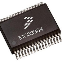
MCZ33904B3EK Freescale Semiconductor, MCZ33904B3EK Datasheet - Page 51

MCZ33904B3EK
Manufacturer Part Number
MCZ33904B3EK
Description
IC SBC CAN HS 3.3V 32SOIC
Manufacturer
Freescale Semiconductor
Type
High Speed CAN Interfacer
Specifications of MCZ33904B3EK
Operating Supply Voltage
3.3 V
Supply Current
2 mA
Package / Case
SOIC-32
Mounting Style
SMD/SMT
Product
CAN
Lead Free Status / RoHS Status
Lead free / RoHS Compliant
Available stocks
Company
Part Number
Manufacturer
Quantity
Price
Company:
Part Number:
MCZ33904B3EKR2
Manufacturer:
FREESCA
Quantity:
4 975
OVERVIEW
occur. The “Safe state” condition is defined by the resistor
connected at the DGB pin. Safe mode is entered after
additional event or conditions are met: time out for CAN
communication and state at I/O-1 pin.
event: in the safe state, the device can automatically be
awakened by CAN and I/O (if configured as inputs). Upon
Wake-up, the device operation is resumed: enter in Reset
mode.
FAIL-SAFE FUNCTIONALITY
(i.e. RST short to VDD), the Safe mode can be entered. In
this mode, the SAFE pin is active low.
Description
condition that make the SAFE pin activated have not
recovered, the device can help to reduce ECU consumption,
assuming that the MCU is not able to set the whole ECU in LP
mode. Two main cases are available:
Mode A
stays ON), until the failure condition recovers (i.e. S/W is able
Exit of Safe Mode
a Wake-up event: in this safe state the device can
automatically awakened by CAN and I/O (if I/O Wake-up was
enable by the SPI prior to enter into SAFE mode). Upon
Analog Integrated Circuit Device Data
Freescale Semiconductor
Fail-safe mode is entered when specific fail conditions
Exiting the safe state is always possible by a Wake-up
Upon dedicated event or issue detected at a device pin
Exit of the safe state with V
Table 9. Fail-safe Options
Upon activation of the SAFE pin, and if the failure
Upon SAFE activation, the MCU remains powered (V
typically 15 k bits [2,1,0) = [110]: verification enable: resistor at DBG pin is typically
typically 33 k bits [2,1,0) = [101]: verification enable: resistor at DBG pin is typically
typically 68 k bits [2,1,0) = [100]: verification enable: resistor at DBG pin is typically
Resistor at
DBG pin
<6.0 k
bits [2,1,0) = [111]: verification enable: resistor at DBG pin is typically
15 kohm (RB1) - Selection of SAFE mode B1
68 kohm (RB3) - Selection of SAFE mode B3
SPI coding - register INIT MISC bits [2,1,0]
33 kohm (RB2 - Selection of SAFE mode B2
0 kohm (RA) - Selection of SAFE mode A
(higher priority that Resistor coding)
DD
OFF is always possible by
FAIL-SAFE OPERATION
DD
to properly control the device and properly refresh the
watchdog).
Modes B1, B2 and B3
external event, and disable the MCU supply (turn V
The external events monitored are: CAN traffic, I/O-1 low
level or both of them. 3 sub cases exist, B1, B2 and B3.
are no longer active, thus that the car is being parked and
stopped. The I/O low level detection can also indicate that the
vehicle is being shutdown, if the I/O-1 pin is connected for
instance to a switched battery signal (ignition key on/off
signal).
hardware, via the resistor connected at DBG pin, but can be
over written by software, via a specific SPI command.
value at DBG pin (upon transition from INIT to Normal mode),
and, if no specific SPI command related to Debug resistor
change is send, operates according to the detected resistor.
device behavior, to either confirm or change the hardware
selected behavior. Device will then operate according to the
SAFE mode configured by the SPI.
Wake-up, the device operation is resumed, and device enters
in Reset mode. The SAFE pin remains active, until there is a
proper read and clear of the SPI flags reporting the SAFE
conditions.
Upon SAFE activation, the system continues to monitor
Note: no CAN traffic indicates that the ECU of the vehicle
The selection of the monitored events is done by
By default, after power up the device detect the resistor
The INIT MISC register allow you to verify and change the
Table 9
Safe mode
code
B1
B2
B3
A
illustrates the complete options available:
BEHAVIOR AT POWER UP AND POWER DOWN
Turn OFF 8.0 s after CAN traffic bus idle detection.
Turn OFF 8.0 s after CAN traffic bus idle detection
Turn OFF when I/O-1 low level detected.
AND when I/O-1 low level detected.
remains ON
V
DD
status
FAIL-SAFE OPERATION
DD
33903/4/5
OFF).
51


