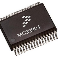
MCZ33904B3EK Freescale Semiconductor, MCZ33904B3EK Datasheet - Page 73

MCZ33904B3EK
Manufacturer Part Number
MCZ33904B3EK
Description
IC SBC CAN HS 3.3V 32SOIC
Manufacturer
Freescale Semiconductor
Type
High Speed CAN Interfacer
Specifications of MCZ33904B3EK
Operating Supply Voltage
3.3 V
Supply Current
2 mA
Package / Case
SOIC-32
Mounting Style
SMD/SMT
Product
CAN
Lead Free Status / RoHS Status
Lead free / RoHS Compliant
Available stocks
Company
Part Number
Manufacturer
Quantity
Price
Company:
Part Number:
MCZ33904B3EKR2
Manufacturer:
FREESCA
Quantity:
4 975
SPECIFIC MODE REGISTER
The SPE MODE Register is used for the Following
Operation
RESET functions.
be extended up to 32 s).
secured SPI command, which consist of 2 commands:
selection or SAFE pin activation:
Normal mode only):
random code)
Analog Integrated Circuit Device Data
Freescale Semiconductor
Table 21. Specific Mode Register, SPE_MODE
- Set the device in RESET mode, to exercise or test the
- Go to INIT mode, using the Secure SPi command.
- Go to FLASH mode (in this mode the watchdog timer can
- Activate the SAFE pin by S/W.
This mode (called Special mode) is accessible from the
1) reading a random code and
2) then write the inverted random code plus mode
Return to INIT mode is done as follow (this is done from
1) Read random code:
MOSI : 0001 0011 0000 0000 [Hex:0x 13 00]
MISO report 16 bits, random code are bits (5-0)
miso = xxxx xxxx xxR5 R4 R3 R2 R1 R0 (RXD = 6 bits
[b_15 b_14] 01_001 [P/N]
b5....b0
b7, b6
MOSI First Byte [15-8]
Bit
Condition for default
00
01
10
11
01 01_ 001 P
Default state
[Rnd_C4b... Rnd_C0b] - Random Code inverted, these six bits are the inverted bits obtained from the SPE MODE Register read command.
Sel_Mod[1], Sel_Mod[0] - Mode selection: these 2 bits are used to select which mode the device will enter upon a SPI command.
Sel_Mod[1]
bit 7
0
Sel_Mod[0]
bit 6
0
Rnd_C5b
bit 5
0
Description
RESET mode
FLASH mode
Rnd_C4b
MOSI Second Byte, bits 7-0
INIT mode
bit 4
HH] (R
mode, with following commands:
random code)
and random code bits 3:0 inverted
HH] (R
to INIT mode, except that the b7 and b6 are set according to
the table above (b7, b6 = 00 - go to reset, b7, b6 = 10 - go to
Flash).
N/A
2) Write INIT mode + random code inverted
MOSI : 0101 0010 01 Ri5 Ri4 Ri3 Ri2 Ri1 Ri0 [Hex 0x 52
MISO : xxxx xxxx xxxx xxxx (don’t care)
SAFE pin activation: SAFE pin can be set low, only in INIT
1) Read random code:
MOSI : 0001 0011 0000 0000 [Hex:0x 13 00]
MISO report 16 bits, random code are bits (5-0)
miso = xxxx xxxx xxR5 R4 R3 R2 R1 R0 (RXD = 6 bits
2) Write INIT mode + random code bits 5:4 not inverted
MOSI : 0101 0010 01 R5 R4 Ri3 Ri2 Ri1 Ri0 [Hex 0x 52
MISO : xxxx xxxx xxxx xxxx (don’t care)
Return to Reset or Flash mode is done similarly to the go
IX
IX
POR
DETAIL OF CONTROL BITS AND REGISTER MAPPING
= random code inverted)
= random code inverted)
Rnd_C3b
bit 3
0
Rnd_C2b
bit 2
0
SERIAL PERIPHERAL INTERFACE
Rnd_C1b
bit 1
0
Rnd_C0b
bit 0
33903/4/5
0
73


