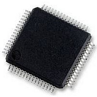
HD64F36077GHV Renesas Electronics America, HD64F36077GHV Datasheet - Page 29

HD64F36077GHV
Manufacturer Part Number
HD64F36077GHV
Description
16BIT MCU FLASH 56K, SMD, LQFP64
Manufacturer
Renesas Electronics America
Datasheet
1.HD64F36077GHV.pdf
(524 pages)
Specifications of HD64F36077GHV
No. Of I/o's
47
Ram Memory Size
4KB
Cpu Speed
20MHz
No. Of Timers
4
Digital Ic Case Style
LQFP
Supply Voltage Range
4.5V
Core Size
16bit
Program Memory Size
56KB
Oscillator Type
External Only
Controller Family/series
H8/300H
Peripherals
ADC
Rohs Compliant
Yes
Lead Free Status / RoHS Status
Lead free / RoHS Compliant
Available stocks
Company
Part Number
Manufacturer
Quantity
Price
Company:
Part Number:
HD64F36077GHV
Manufacturer:
RENESAS
Quantity:
340
Part Number:
HD64F36077GHV
Manufacturer:
RENESAS/瑞萨
Quantity:
20 000
- Current page: 29 of 524
- Download datasheet (4Mb)
Table 16.6
Table 16.7
Section 17 I
Table 17.1
Table 17.2
Table 17.3
Table 17.4
Section 18 A/D Converter
Table 18.1
Table 18.2
Table 18.3
Section 19 Band-Gap Circuit, Power-On Reset, and Low-Voltage Detection Circuits
Table 19.1
Table 19.2
Section 22 Electrical Characteristics
Table 22.1
Table 22.2
Table 22.2
Table 22.3
Table 22.4
Table 22.5
Table 22.6
Table 22.7
Table 22.8
Table 22.9
Table 22.10
Table 22.11
Appendix
Table A.1
Table A.2
Table A.2
Table A.2
Table A.3
Table A.4
Table A.5
2
C Bus Interface 2 (IIC2)
SSR Status Flags and Receive Data Handling ...................................................... 300
SCI3 Interrupt Requests........................................................................................ 317
I
Transfer Rate ........................................................................................................ 326
Interrupt Requests ................................................................................................. 354
Time for Monitoring SCL..................................................................................... 355
Pin Configuration.................................................................................................. 359
Analog Input Channels and Corresponding ADDR Registers .............................. 360
A/D Conversion Time (Single Mode)................................................................... 365
LVDCR Settings and Select Functions................................................................. 373
Deciding Reset Source.......................................................................................... 382
Absolute Maximum Ratings ................................................................................. 405
DC Characteristics (1)........................................................................................... 409
DC Characteristics (2)........................................................................................... 414
AC Characteristics ................................................................................................ 415
I
Serial Communication Interface (SCI) Timing..................................................... 418
A/D Converter Characteristics .............................................................................. 419
Watchdog Timer Characteristics........................................................................... 420
Flash Memory Characteristics .............................................................................. 421
Power-Supply-Voltage Detection Circuit Characteristics..................................... 423
Instruction Set ....................................................................................................... 431
Operation Code Map (1) ....................................................................................... 444
Operation Code Map (2) ....................................................................................... 445
Operation Code Map (3) ....................................................................................... 446
Number of Cycles in Each Instruction.................................................................. 448
Number of Cycles in Each Instruction.................................................................. 449
Combinations of Instructions and Addressing Modes .......................................... 458
2
2
C Bus Interface Pins........................................................................................... 323
C Bus Interface Timing ...................................................................................... 417
LVDI External Input Voltage Detection Circuit Characteristics ...................... 423
Power-On Reset Circuit Characteristics............................................................ 424
Rev. 1.00 Sep. 16, 2005 Page xxix of xxx
Related parts for HD64F36077GHV
Image
Part Number
Description
Manufacturer
Datasheet
Request
R

Part Number:
Description:
KIT STARTER FOR M16C/29
Manufacturer:
Renesas Electronics America
Datasheet:

Part Number:
Description:
KIT STARTER FOR R8C/2D
Manufacturer:
Renesas Electronics America
Datasheet:

Part Number:
Description:
R0K33062P STARTER KIT
Manufacturer:
Renesas Electronics America
Datasheet:

Part Number:
Description:
KIT STARTER FOR R8C/23 E8A
Manufacturer:
Renesas Electronics America
Datasheet:

Part Number:
Description:
KIT STARTER FOR R8C/25
Manufacturer:
Renesas Electronics America
Datasheet:

Part Number:
Description:
KIT STARTER H8S2456 SHARPE DSPLY
Manufacturer:
Renesas Electronics America
Datasheet:

Part Number:
Description:
KIT STARTER FOR R8C38C
Manufacturer:
Renesas Electronics America
Datasheet:

Part Number:
Description:
KIT STARTER FOR R8C35C
Manufacturer:
Renesas Electronics America
Datasheet:

Part Number:
Description:
KIT STARTER FOR R8CL3AC+LCD APPS
Manufacturer:
Renesas Electronics America
Datasheet:

Part Number:
Description:
KIT STARTER FOR RX610
Manufacturer:
Renesas Electronics America
Datasheet:

Part Number:
Description:
KIT STARTER FOR R32C/118
Manufacturer:
Renesas Electronics America
Datasheet:

Part Number:
Description:
KIT DEV RSK-R8C/26-29
Manufacturer:
Renesas Electronics America
Datasheet:

Part Number:
Description:
KIT STARTER FOR SH7124
Manufacturer:
Renesas Electronics America
Datasheet:

Part Number:
Description:
KIT STARTER FOR H8SX/1622
Manufacturer:
Renesas Electronics America
Datasheet:


