IPR-RLDII/UNI Altera, IPR-RLDII/UNI Datasheet - Page 48
IPR-RLDII/UNI
Manufacturer Part Number
IPR-RLDII/UNI
Description
IP CORE Renewal Of IP-RLDII/UNI
Manufacturer
Altera
Datasheet
1.IP-RLDIIUNI.pdf
(76 pages)
Specifications of IPR-RLDII/UNI
Software Application
IP CORE, Memory Controllers, SDRAM
Supported Families
Arria II GZ, Stratix III, Stratix IV, HardCopy III
Core Architecture
FPGA
Core Sub-architecture
Arria, HardCopy, Stratix
Rohs Compliant
NA
Lead Free Status / RoHS Status
na


6–8
External Memory Interface Handbook Volume 3
Section IV. RLDRAM II Controller with UniPHY IP User Guide
The DLL and PLL Sharing Interface
1
1
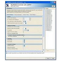
You can generate the UniPHY memory interface as a master or as a slave, depending
on the setting of the Master for PLL/DLL sharing option on the General Settings tab
of the parameter editor. The top level of a generated UniPHY variant contains both a
PLL and a DLL; the PLL produces a variety of required clock signals derived from the
reference clock, and the DLL produces a delay codeword. The top-level defines the
PLL and DLL output signals as outputs for the master and as inputs for the slave.
When you instantiate master and slave variants into your HDL code, you must
connect the PLL outputs from the master to the clock inputs of the slaves.
The master .qip file must appear before the slave .qip file in the Quartus II Settings
File (.qsf).
The UniPHY memory interface requires one PLL and one DLL to produce the clocks
and delay codeword. The PLL and DLL can be shared using a master and slave
scenario. The top-level file defines the PLL and DLL output signals as inputs and
outputs and an additional parameter PLL_DLL_MASTER is also defined. If
PLL_DLL_MASTER is 1, the RTL instantiates the PLL and DLL, which drives the clock
and DLL codeword inputs and outputs. If the parameter is 0, the wires previously
connected to the output of the PLL and DLL are assigned to the clock and DLL
codeword input and outputs. Inputs and outputs are specified based on the setting of
the PLL/DLL sharing option.
If you generate a slave IP core, you must modify the timing scripts to allow the timing
analysis to correctly resolve clock names and analyze the IP core. Otherwise the
software issues critical warnings and an incorrect timing report.
To modify the timing script, follow these steps:
1. In a text editor, open the <IP core name>/constraints directory/<IP core
2. Search for the following 2 lines:
3. Replace _MASTER_CORE_ with the core name and _MASTER_INST_ with instance
4. If the slave component is connected to a user-defined PLL rather than a UniPHY
name>_timing.tcl file.
■
■
name of the UniPHY master to which the slave is connected.
1
master, you must manually enter all clock names.
■
■
set master_corename "_MASTER_CORE_"
set master_instname "_MASTER_INST_"
Remove the master_corename and master_instname variables with the checks
performed in the eight lines following them.
You can use all clock name assignments as templates. For example set
local_pll_afi_clk "mycomponent|mypll|my_afi_clk".
The instance name is the full path to the instance and is in the <IP core
name>_all_pins.txt file that is automatically generated after the <IP core
name>_pin_assignments.tcl script runs.
Chapter 6: Functional Description—UniPHY
December 2010 Altera Corporation
Interfaces
Related parts for IPR-RLDII/UNI
Image
Part Number
Description
Manufacturer
Datasheet
Request
R

Part Number:
Description:
IP CORE Renewal Of IP-XAUIPCS
Manufacturer:
Altera
Datasheet:

Part Number:
Description:
CYCLONE II STARTER KIT EP2C20N
Manufacturer:
Altera
Datasheet:

Part Number:
Description:
CPLD, EP610 Family, ECMOS Process, 300 Gates, 16 Macro Cells, 16 Reg., 16 User I/Os, 5V Supply, 35 Speed Grade, 24DIP
Manufacturer:
Altera Corporation
Datasheet:
Part Number:
Description:
CPLD, EP610 Family, ECMOS Process, 300 Gates, 16 Macro Cells, 16 Reg., 16 User I/Os, 5V Supply, 15 Speed Grade, 24DIP
Manufacturer:
Altera Corporation
Datasheet:
Part Number:
Description:
Manufacturer:
Altera Corporation
Datasheet:
Part Number:
Description:
CPLD, EP610 Family, ECMOS Process, 300 Gates, 16 Macro Cells, 16 Reg., 16 User I/Os, 5V Supply, 30 Speed Grade, 24DIP
Manufacturer:
Altera Corporation
Datasheet:
Part Number:
Description:
High-performance, low-power erasable programmable logic devices with 8 macrocells, 10ns
Manufacturer:
Altera Corporation
Datasheet:
Part Number:
Description:
High-performance, low-power erasable programmable logic devices with 8 macrocells, 7ns
Manufacturer:
Altera Corporation
Datasheet:
Part Number:
Description:
Classic EPLD
Manufacturer:
Altera Corporation
Datasheet:
Part Number:
Description:
High-performance, low-power erasable programmable logic devices with 8 macrocells, 10ns
Manufacturer:
Altera Corporation
Datasheet:
Part Number:
Description:
Manufacturer:
Altera Corporation
Datasheet:
Part Number:
Description:
Manufacturer:
Altera Corporation
Datasheet: