IPR-RLDII/UNI Altera, IPR-RLDII/UNI Datasheet - Page 69
IPR-RLDII/UNI
Manufacturer Part Number
IPR-RLDII/UNI
Description
IP CORE Renewal Of IP-RLDII/UNI
Manufacturer
Altera
Datasheet
1.IP-RLDIIUNI.pdf
(76 pages)
Specifications of IPR-RLDII/UNI
Software Application
IP CORE, Memory Controllers, SDRAM
Supported Families
Arria II GZ, Stratix III, Stratix IV, HardCopy III
Core Architecture
FPGA
Core Sub-architecture
Arria, HardCopy, Stratix
Rohs Compliant
NA
Lead Free Status / RoHS Status
na


Table 8–1. Latency (In Full-Rate Memory Clock Cycles)
December 2010 Altera Corporation
Notes to
(1) Even write latency.
(2) Odd write latency.
(3) Latency is the number of cycles between the first register of the current stage capturing cmd/data, and the first register in the next stage
(4) Latency shown is best case, for maximum performance specifications. Latency may be higher due to protocol requirements; controller latency
capturing cmd/data.
may be lower for slower frequencies.
Rate
Half
Full
Table
Variable Controller Latency
8–1:
1
Command
Address and
Controller
Altera defines read and write latencies in terms of memory clock cycles. These
latencies apply to supported device families
There are two types of latencies that exists while designing with memory
controllers—read and write latencies, which have the following definitions:
■
■
For a half-rate controller, the local side frequency is half of the memory interface
frequency. For a full-rate controller, the local side frequency is equal to the memory
interface frequency.
Table 8–1
.
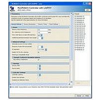
The variable controller latency feature allows you to take advantage of lower latency
for variations designed to run at lower frequency. When deciding whether to vary the
controller latency from the default value of 2, be aware of the following
considerations:
■
■
If you select a latency value that is inappropriate for the target frequency, the system
displays a warning message in the text area at the bottom of the parameter editor.
2
4
Read latency—the amount of time it takes for the read data to appear at the local
interface after initiating the read request.
Write latency—the amount of time it takes for the write data to appear at the
memory interface after initiating the write request.
Reduced latency can help achieve a reduction in resource usage and clock cycles in
the controller, but might result in lower f
Increased latency can help achieve greater f
cycles in the controller and result in increased resource usage.
(4)
shows the latency in full rate memory clock cycles.
and Command
PHY Address
1
2
1
(2)
(1)
Maximum
Memory
(Note 3)
Read
3–8
3–8
Section IV. RLDRAM II Controller with UniPHY IP User Guide
PHY Read
MAX
(Table 1–2 on page
Return
MAX
4
7
.
, but may consume more clock
External Memory Interface Handbook Volume 3
Round Trip
16–20
16–18
10–15
1–2).
(2)
(1)
8. Latency
Round Trip
Memory
without
12
13
7
(2)
(1)
Related parts for IPR-RLDII/UNI
Image
Part Number
Description
Manufacturer
Datasheet
Request
R

Part Number:
Description:
IP CORE Renewal Of IP-XAUIPCS
Manufacturer:
Altera
Datasheet:

Part Number:
Description:
CYCLONE II STARTER KIT EP2C20N
Manufacturer:
Altera
Datasheet:

Part Number:
Description:
CPLD, EP610 Family, ECMOS Process, 300 Gates, 16 Macro Cells, 16 Reg., 16 User I/Os, 5V Supply, 35 Speed Grade, 24DIP
Manufacturer:
Altera Corporation
Datasheet:
Part Number:
Description:
CPLD, EP610 Family, ECMOS Process, 300 Gates, 16 Macro Cells, 16 Reg., 16 User I/Os, 5V Supply, 15 Speed Grade, 24DIP
Manufacturer:
Altera Corporation
Datasheet:
Part Number:
Description:
Manufacturer:
Altera Corporation
Datasheet:
Part Number:
Description:
CPLD, EP610 Family, ECMOS Process, 300 Gates, 16 Macro Cells, 16 Reg., 16 User I/Os, 5V Supply, 30 Speed Grade, 24DIP
Manufacturer:
Altera Corporation
Datasheet:
Part Number:
Description:
High-performance, low-power erasable programmable logic devices with 8 macrocells, 10ns
Manufacturer:
Altera Corporation
Datasheet:
Part Number:
Description:
High-performance, low-power erasable programmable logic devices with 8 macrocells, 7ns
Manufacturer:
Altera Corporation
Datasheet:
Part Number:
Description:
Classic EPLD
Manufacturer:
Altera Corporation
Datasheet:
Part Number:
Description:
High-performance, low-power erasable programmable logic devices with 8 macrocells, 10ns
Manufacturer:
Altera Corporation
Datasheet:
Part Number:
Description:
Manufacturer:
Altera Corporation
Datasheet:
Part Number:
Description:
Manufacturer:
Altera Corporation
Datasheet: