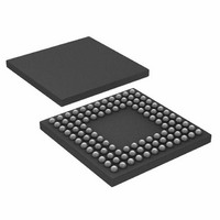
ADUC7121BBCZ-RL Analog Devices Inc, ADUC7121BBCZ-RL Datasheet - Page 44

ADUC7121BBCZ-RL
Manufacturer Part Number
ADUC7121BBCZ-RL
Description
PRECISION ANALOG MCU I.C
Manufacturer
Analog Devices Inc
Series
MicroConverter® ADuC7xxxr
Datasheet
1.ADUC7121BBCZ.pdf
(96 pages)
Specifications of ADUC7121BBCZ-RL
Core Processor
ARM7
Core Size
16/32-Bit
Speed
41.78MHz
Connectivity
I²C, SPI, UART/USART
Peripherals
POR, PWM, WDT
Number Of I /o
32
Program Memory Size
126KB (63K x 16)
Program Memory Type
FLASH
Ram Size
8K x 8
Voltage - Supply (vcc/vdd)
3 V ~ 3.6 V
Data Converters
A/D 9x12b, D/A 4x12b
Oscillator Type
Internal
Operating Temperature
-10°C ~ 95°C
Package / Case
108-LFBGA, CSPBGA
Lead Free Status / RoHS Status
Lead free / RoHS Compliant
Eeprom Size
-
Lead Free Status / RoHS Status
Lead free / RoHS Compliant
Other names
ADUC7121BBCZ-RL
ADUC7121BBCZ-RLTR
ADUC7121BBCZ-RLTR
Available stocks
Company
Part Number
Manufacturer
Quantity
Price
Company:
Part Number:
ADUC7121BBCZ-RL
Manufacturer:
Analog Devices Inc
Quantity:
10 000
ADuC7121
The reference current of each IDAC is generated by a precision
internal band gap voltage reference and an external precision
resistor, and as such, the gain error of each IDAC is impacted by
the accuracy of the external resistor. Connect the resistor to the
I
capacitor, C
as to meet the signal bandwidth. Connect C
An NMOS switch is provided to shut down the IDAC0 diode.
Note that the output current switches off while this switch is on.
When the switch is on, the IDAC0 pin is able to withstand −0.5 V.
At power-up or reset, IDAC0 is powered down by default and
its output is high impedance. When enabled, the IDAC0 output
current does not overshoot.
To reduce the heat dissipation on chip, a separate power supply
can be used. An internal LDO provides a stable 2.5 V supply for
all low current internal IDACs.
Precision Current Generation and Fault Protection
The reference current is generated either from an on-chip
precision band gap voltage source or from an external voltage
reference by default, which is applied to an external precision
resistor. This resistor is connected to the I
is factory trimmed to obtain a precise initial value and low
temperature drift. The external resistor is an assumed 0.1%
accuracy with 5 ppm drift, and a 0.1 μF external capacitor is
required to bypass high frequency noise.
A fault detection block is included to stop problems from occurring
if too small a reference resistor is detected. By sending the devel-
oped reference current into an on-board resistor of half the
expected size of the external resistor, a fault signal is generated
if the resistor is less than half the expected value (to an accuracy
REF
pin. The noise of each IDAC is limited by its damping
DAMP
, which is selected to band limit noise as well
DAMP
REF
pin. The band gap
_IDACx to PGND.
Rev. 0 | Page 44 of 96
of about 20%). The external resistor value is calculated by R
V
reference voltage for the voltage-to-current circuit.
IDAC and Output Stage Fault Protection
All five IDACs use the same architecture to generate high-side
current whereby only the section that generates the reference
current is shared. A low current is generated first using a current-
mode DAC, which is then mirrored up to give the large output
current that is desired. A thermal shutdown circuit protects the
chip from overheating. The IDACs are guaranteed monotonic
to within 11 bits of resolution.
The bandwidth limit is provided by a programmable internal
resistor and an external capacitor. This is to filter high frequency
noise. It is also used to generate a triangle wave from a square
wave input for the IDAC4 only.
The thermal shutdown circuit automatically shuts down all of
the output stages when the chip temperature exceeds a certain
threshold. The intention of the thermal shutdown is only for
protection in the case of a short on an IDAC output. The over-
heating of the chip from other causes also triggers a thermal
shutdown but only the IDAC output stage is automatically shut
down. It triggers an interrupt and sets the TSHUT bit in the
IDACSTA register to indicate the overheating of the chip.
In case the digital core malfunctions at a temperature lower
than the thermal shutdown trigger point, the circuit can still
shut down the IDAC, but a watchdog reset must be used to reset
the chip. The TSHUT bit retains its value after a software reset
or a watchdog reset. This bit can only be cleared by a power-on
reset, a hardware reset, or when 0 is written to the IDACSTA
register.
REF
/I
REF
, where I
REF
= 370.37 μA and V
REF
is the selected
EXT
=


