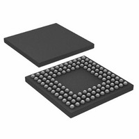
ADUC7121BBCZ-RL Analog Devices Inc, ADUC7121BBCZ-RL Datasheet - Page 74

ADUC7121BBCZ-RL
Manufacturer Part Number
ADUC7121BBCZ-RL
Description
PRECISION ANALOG MCU I.C
Manufacturer
Analog Devices Inc
Series
MicroConverter® ADuC7xxxr
Datasheet
1.ADUC7121BBCZ.pdf
(96 pages)
Specifications of ADUC7121BBCZ-RL
Core Processor
ARM7
Core Size
16/32-Bit
Speed
41.78MHz
Connectivity
I²C, SPI, UART/USART
Peripherals
POR, PWM, WDT
Number Of I /o
32
Program Memory Size
126KB (63K x 16)
Program Memory Type
FLASH
Ram Size
8K x 8
Voltage - Supply (vcc/vdd)
3 V ~ 3.6 V
Data Converters
A/D 9x12b, D/A 4x12b
Oscillator Type
Internal
Operating Temperature
-10°C ~ 95°C
Package / Case
108-LFBGA, CSPBGA
Lead Free Status / RoHS Status
Lead free / RoHS Compliant
Eeprom Size
-
Lead Free Status / RoHS Status
Lead free / RoHS Compliant
Other names
ADUC7121BBCZ-RL
ADUC7121BBCZ-RLTR
ADUC7121BBCZ-RLTR
Available stocks
Company
Part Number
Manufacturer
Quantity
Price
Company:
Part Number:
ADUC7121BBCZ-RL
Manufacturer:
Analog Devices Inc
Quantity:
10 000
ADuC7121
Table 97. SPISTA MMR Bit Designations
Bit
15:12
11
10:8
7
6
5
4
3:1
0
SPIRX Register
This 8-bit MMR is the SPI receive register.
Name:
Address:
Default value:
Access:
SPITX Register
This 8-bit MMR is the SPI transmit register.
Name:
Address:
Default value:
Access:
Name
SPIREX
SPIRXFSTA[2:0]
SPIFOF
SPIRXIRQ
SPITXIRQ
SPITXUF
SPITXFSTA[2:0]
SPIISTA
SPIRX
0xFFFF0A04
0x00
Read only
SPITX
0xFFFF0A08
0x00
Write only
Description
Reserved bits.
SPI Rx FIFO excess bytes present. This bit is set when there are more bytes in the Rx FIFO than indicated in the
SPIMDE bits in SPICON.
This bit is cleared when the number of bytes in the FIFO is equal or less than the number in SPIMDE.
SPI Rx FIFO status bits.
[000] = Rx FIFO is empty.
[001] = one valid byte in the FIFO.
[010] = two valid bytes in the FIFO.
[011] = three valid bytes in the FIFO.
[100] = four valid bytes in the FIFO.
SPI Rx FIFO overflow status bit.
Set when the Rx FIFO was already full when new data was loaded to the FIFO. This bit generates an interrupt
except when SPIRFLH is set in SPICON.
Cleared when the SPISTA register is read.
SPI Rx IRQ status bit.
Set when a receive interrupt occurs. This bit is set when SPITMDE in SPICON is cleared and the required
number of bytes have been received.
Cleared when the SPISTA register is read.
SPI Tx IRQ status bit.
Set when a transmit interrupt occurs. This bit is set when SPITMDE in SPICON is set and the required number
of bytes have been transmitted.
Cleared when the SPISTA register is read.
SPI Tx FIFO underflow.
This bit is set when a transmit is initiated without any valid data in the Tx FIFO. This bit generates an interrupt
except when SPITFLH is set in SPICON.
Cleared when the SPISTA register is read.
SPI Tx FIFO status bits.
[000] = Tx FIFO is empty.
[001] = one valid byte in the FIFO.
[010] = two valid bytes in the FIFO.
[011] = three valid bytes in the FIFO.
[100] = four valid bytes in the FIFO.
SPI interrupt status bit.
Set to 1 when an SPI based interrupt occurs.
Cleared after reading SPISTA.
Rev. 0 | Page 74 of 96
SPIDIV Register
This 8-bit MMR is the SPI baud rate selection register.
Name:
Address:
Default value:
Access:
SPI Control Register
This 16-bit MMR configures the SPI peripheral in both master
and slave modes.
Name:
Address:
Default value:
Access:
SPIDIV
0xFFFF0A0C
0x00
Read and write
SPICON
0xFFFF0A10
0x0000
Read and write


