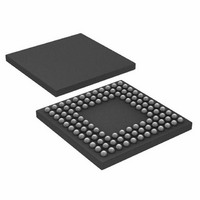
ADUC7121BBCZ-RL Analog Devices Inc, ADUC7121BBCZ-RL Datasheet - Page 83

ADUC7121BBCZ-RL
Manufacturer Part Number
ADUC7121BBCZ-RL
Description
PRECISION ANALOG MCU I.C
Manufacturer
Analog Devices Inc
Series
MicroConverter® ADuC7xxxr
Datasheet
1.ADUC7121BBCZ.pdf
(96 pages)
Specifications of ADUC7121BBCZ-RL
Core Processor
ARM7
Core Size
16/32-Bit
Speed
41.78MHz
Connectivity
I²C, SPI, UART/USART
Peripherals
POR, PWM, WDT
Number Of I /o
32
Program Memory Size
126KB (63K x 16)
Program Memory Type
FLASH
Ram Size
8K x 8
Voltage - Supply (vcc/vdd)
3 V ~ 3.6 V
Data Converters
A/D 9x12b, D/A 4x12b
Oscillator Type
Internal
Operating Temperature
-10°C ~ 95°C
Package / Case
108-LFBGA, CSPBGA
Lead Free Status / RoHS Status
Lead free / RoHS Compliant
Eeprom Size
-
Lead Free Status / RoHS Status
Lead free / RoHS Compliant
Other names
ADUC7121BBCZ-RL
ADUC7121BBCZ-RLTR
ADUC7121BBCZ-RLTR
Available stocks
Company
Part Number
Manufacturer
Quantity
Price
Company:
Part Number:
ADUC7121BBCZ-RL
Manufacturer:
Analog Devices Inc
Quantity:
10 000
VIC MMRs
IRQBASE Register
The vector base register, IRQBASE, is used to point to the start
address of memory used to store 32 pointer addresses. These
pointer addresses are the addresses of the individual interrupt
service routines.
Name:
Address:
Default value:
Access:
Table 110. IRQBASE MMR Bit Designations
Bit
31:16
15:0
IRQVEC Register
The IRQ interrupt vector register, IRQVEC points to a memory
address containing a pointer to the interrupt service routine of
the currently active IRQ. Read this register only when an IRQ
occurs and IRQ interrupt nesting has been enabled by setting
Bit 0 of the IRQCONN register.
Name:
Address:
Default value:
Access:
Table 111. IRQVEC MMR Bit Designations
Bit
31:23
22:7
6:2
1:0
Priority Registers
IRQP0 Register
Name:
Address:
Default value:
Access:
Type
Read only
Read and
write
Read only
Reserved
Type
Read only
Read and write
IRQBASE
0x00000000
Read and write
IRQVEC
0x00000000
Read and write
IRQP0
0x00000000
Read and write
0xFFFF0014
0xFFFF001C
0xFFFF0020
Initial
Value
0
0
0
0
Initial Value
Reserved
0
Description
Always read as 0.
IRQBASE register value.
Highest priority source. This is a
value between 0 and 27
representing the possible
interrupt sources. For example, if
the highest currently active IRQ is
Timer2, these bits are [00100].
Reserved bits.
Description
Always read as 0
Vector base address
Rev. 0 | Page 83 of 96
Table 112. IRQP0 MMR Bit Designations
Bit
31
30:28
27
26:24
23
22:20
19
18:16
15
14:12
11
10:8
7
6:4
3:0
IRQP1 Register
Name:
Address:
Default value:
Access:
Table 113. IRQP1 MMR Bit Designations
Bit
31
30:28
27
26:24
23
22:20
19
18:16
15
14:12
11
10:8
7:3
2:0
Name
Reserved
IDAC_Fault
Reserved
T4PI
Reserved
T3PI
Reserved
T2PI
Reserved
T1PI
Reserved
T0PI
Reserved
SWINTP
Reserved
Name
Reserved
I2C0MPI
Reserved
SPIPI
Reserved
UARTPI
Reserved
ADCPI
Reserved
Flash1PI
Reserved
Flash0PI
Reserved
PSMPI
IRQP1
0xFFFF0024
0x00000000
Read and write
Description
Reserved bit.
A priority level of 0 to 7 can be set for I
master.
Reserved bit.
A priority level of 0 to 7 can be set for SPI.
Reserved bit.
A priority level of 0 to 7 can be set for UART.
Reserved bit.
A priority level of 0 to 7 can be set for the
ADC interrupt source.
Reserved bit.
A priority level of 0 to 7 can be set for the
Flash block 1 controller interrupt source.
Reserved bit.
A priority level of 0 to 7 can be set for the
Flash Block 0 controller interrupt source.
Reserved bits.
A priority level of 0 to 7 can be set for the
power supply monitor interrupt source.
Description
Reserved bit.
A priority level of 0 to 7 can be set for an
IDAC fault interrupt.
Reserved bit.
A priority level of 0 to 7 can be set for
Timer4.
Reserved bit.
A priority level of 0 to 7 can be set for
Timer3.
Reserved bit.
A priority level of 0 to 7 can be set for
Timer2.
Reserved bit.
A priority level of 0 to 7 can be set for
Timer1.
Reserved bit.
A priority level of 0 to 7 can be set for
Timer0.
Reserved bit.
A priority level of 0 to 7 can be set for the
software interrupt source.
Reserved bit.
ADuC7121
2
C 0


