CYIL2SM1300AA-GZDC Cypress Semiconductor Corp, CYIL2SM1300AA-GZDC Datasheet - Page 34
CYIL2SM1300AA-GZDC
Manufacturer Part Number
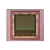
CYIL2SM1300AA-GZDC
Description
IMAGE SENSOR CMOS LUPA-1300-3
Manufacturer
Cypress Semiconductor Corp
Type
CMOS Imagingr
Specifications of CYIL2SM1300AA-GZDC
Package / Case
168-PGA
Pixel Size
14µm x 14µm
Active Pixel Array
1280H x 1024V
Frames Per Second
500
Voltage - Supply
2.5V, 3.3V
Operating Supply Voltage
2.5 V
Maximum Power Dissipation
1350 mW
Maximum Operating Temperature
+ 70 C
Supply Current
80 mA
Minimum Operating Temperature
0 C
Package
168CuPGA
Image Size
1280x1024 Pixels
Color Sensing
Monochrome
Operating Temperature
0 to 70 °C
Lead Free Status / RoHS Status
Lead free / RoHS Compliant
Lead Free Status / RoHS Status
Lead free / RoHS Compliant, Lead free / RoHS Compliant


Full Frame Mode
In this operation mode, the entire sensor shown in
sequencer, and the behavior of the data and sync channels (overview and detail of one line).
Off Chip Automatic Black Level Calibration
The last time slot not only contains valid pixels but also two
dummy columns, six grey columns, and eight black columns.
The grey column values are used to perform off chip black level
calibration to maintain a constant black level against any type of
drift. These values gauge the response of normal pixels in the
dark conditions.
Grey columns are generated by applying a minimal integration
time (black timer register) to the columns. Black columns share
the same minimal integration time; additionally, the pixels in that
column are shielded. Grey columns can be used if the integration
time is large compared to the minimal integration time. Black
columns are used if the integration time is in the same order of
magnitude as the minimal integration time.
Document Number: 001-24599 Rev. *F
Data channel
Data channel
Sync Channel
Data Channel
Sync Channel
Sync Channel
Data Channel
Sync Channel
Sequencer
internal state
Sequencer
internal state
Figure 34. Full Frame Mode Readout with On Chip Black Level Calibration Disabled
FOT ROT
FOT ROT
T
T
T
T
FS
FS
timeslot timeslot timeslot
timeslot timeslot timeslot
Figure 33. Full Frame Mode Readout
black
black
1
1
D
D
D
D
ROT
ROT
Figure 18
2
2
D
D
line 0
line 0
D
D
3
3
D
D
on page 24 is read out.
ROT
ROT
The procedure is as follows:
1. Decide what digital code should be the desired black level.
2. Set the sensor to safe settings; DACVREFADC must be on a
3. Read-out the grey (or black) columns.
4. Calculate the average value of this grey (or black) data; also
5. Adapt the DACVREFADC if the calculated value deviate from
6. Repeat the procedure for temperature changes.
❐
❐
0x00 cannot be chosen to avoid underflow in FPN correction.
value that never clips the grey (or black) columns.
average it out over the different grey columns.
the desired black level value and return to step (2).
line 1
line 1
Make sure that the grey (or black) columns can be read out
without clipping.
Make sure that this is the case for every sensor including
dc-shifts due to Vt and temperature differences.
D
D
timeslot
timeslot
line
53
line
53
1022
1022
D GB LE CR
D
Figure 33
D
ROT
ROT
timeslot
timeslot
54
54
LE CR
line
line
1023
1023
shows the internal state of the
timeslot
timeslot
C
C
CRC
CRC
CYIL2SM1300AA
T
T
T
T
Page 34 of 43
[+] Feedback
Related parts for CYIL2SM1300AA-GZDC
Image
Part Number
Description
Manufacturer
Datasheet
Request
R

Part Number:
Description:
BOARD EVAL IMG SENS LUPA-1300-2
Manufacturer:
Cypress Semiconductor Corp
Datasheet:
Part Number:
Description:
Manufacturer:
Cypress Semiconductor Corp
Datasheet:
Part Number:
Description:
Manufacturer:
Cypress Semiconductor Corp
Datasheet:
Part Number:
Description:
Manufacturer:
Cypress Semiconductor Corp
Datasheet:
Part Number:
Description:
Manufacturer:
Cypress Semiconductor Corp
Datasheet:
Part Number:
Description:
Manufacturer:
Cypress Semiconductor Corp
Datasheet: