8808A 120V Fluke Electronics, 8808A 120V Datasheet - Page 35
8808A 120V
Manufacturer Part Number
8808A 120V
Description
DMM 5.5 RES RS-232 INTERFACE
Manufacturer
Fluke Electronics
Type
Digital (DMM)r
Specifications of 8808A 120V
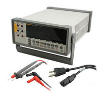
Includes
Test Leads
Style
Bench
Display Digits
5.5
Display Type
VFD, Dual
Display Count
200000
Function
Voltage, Current, Resistance, Frequency
Functions, Extra
Continuity, dB, Diode Test
Features
Hold, Min/Max, RS-232 Port
Ranging
Auto/Manual
Response
True RMS
Lead Free Status / RoHS Status
Not applicable / RoHS non-compliant
Other names
614-1068


Operating the Meter from the Front Panel
Introduction........................................................................................................ 3-3
Dual Display ...................................................................................................... 3-6
Rear Panel .......................................................................................................... 3-8
Adjusting Meter Range ...................................................................................... 3-8
Selecting a Measurement Rate........................................................................... 3-9
Selecting a Measurement Function.................................................................... 3-9
Selecting a Function Modifier ........................................................................... 3-17
Compare Function (COMP)............................................................................... 3-22
List and Number Editors.................................................................................... 3-22
Function Keys S1 – S6....................................................................................... 3-24
Power-Up Configuration.................................................................................... 3-25
Primary Display............................................................................................. 3-6
Secondary Display......................................................................................... 3-6
Measuring Voltage ........................................................................................ 3-10
Measuring Frequency .................................................................................... 3-10
Frequency Ranging........................................................................................ 3-11
Measuring Resistance .................................................................................... 3-11
Measuring Current......................................................................................... 3-13
Automatic Input Terminal Detection............................................................. 3-14
Diode / Continuity Testing ............................................................................ 3-15
Making a Triggered Measurement ................................................................ 3-16
Relative Readings Modifier (REL)................................................................ 3-18
Decibels and Auto Power Modifier ............................................................... 3-18
Touch Hold Function (HOLD) ...................................................................... 3-19
Minimum / Maximum Modifier (MIN MAX) .............................................. 3-20
Using the Function Modifiers in Combination.............................................. 3-21
Second Level Operations (Using the SHIFT Button).................................... 3-21
Setting the Compare Range ........................................................................... 3-22
Using the Compare Function......................................................................... 3-22
Using the List Editor ..................................................................................... 3-23
Using the Number Editor............................................................................... 3-24
2-Wire Resistance Measurement............................................................... 3-11
4-Wire Resistance Measurement............................................................... 3-12
Setting the Trigger Mode .......................................................................... 3-16
Connecting to an External Trigger ............................................................ 3-16
Title
Chapter 3
Page
3-1