8808A 120V Fluke Electronics, 8808A 120V Datasheet - Page 9
8808A 120V
Manufacturer Part Number
8808A 120V
Description
DMM 5.5 RES RS-232 INTERFACE
Manufacturer
Fluke Electronics
Type
Digital (DMM)r
Specifications of 8808A 120V
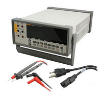
Includes
Test Leads
Style
Bench
Display Digits
5.5
Display Type
VFD, Dual
Display Count
200000
Function
Voltage, Current, Resistance, Frequency
Functions, Extra
Continuity, dB, Diode Test
Features
Hold, Min/Max, RS-232 Port
Ranging
Auto/Manual
Response
True RMS
Lead Free Status / RoHS Status
Not applicable / RoHS non-compliant
Other names
614-1068


2-1.
2-2.
2-3.
2-4.
2-5.
3-1.
3-2.
3-3.
3-4.
3-5.
3-6.
3-7.
3-8.
3-9.
3-10. Continuity Test....................................................................................................... 3-15
3-11. Diode Test .............................................................................................................. 3-16
3-12. External Trigger Circuit ......................................................................................... 3-17
4-1.
4-2.
4-3.
4-4.
A-1. Example of Dual Display Showing Volts AC and Frequency ............................... A-2
A-2. DC Voltage and DC Current Measurement on Input Signal.................................. A-4
A-3. Shunt Method of Low-Level Current Measurement .............................................. A-8
A-4. Zero Burden Voltage Low-Level Current Measurement ....................................... A-8
B-1. 2X4 Wire Test Leads ............................................................................................. B-2
Replacing the Line Power Fuse.............................................................................. 2-5
Replacing the Current-Input Fuses......................................................................... 2-6
Line-Power Cord Types Available from Fluke...................................................... 2-7
Bail Adjustment and Removal ............................................................................... 2-8
Boot removal.......................................................................................................... 2-9
Front Panel ............................................................................................................. 3-4
Display Annunciators and Indicators ..................................................................... 3-6
Rear Panel .............................................................................................................. 3-8
Voltage and Frequency Measurement.................................................................... 3-10
2-Wire Resistance Measurement............................................................................ 3-11
4-Wire Resistance Measurement............................................................................ 3-12
Input Connections for 4-wire ohms using 2x4 wire leads...................................... 3-13
Current Measurement <200 mA............................................................................. 3-14
Current Measurement 200 mA to 10 A .................................................................. 3-14
External Trigger Using Pin 9 of RS-232 Interface................................................. 4-10
Overview of Status Data Structures ....................................................................... 4-12
Event Status and Event Status Enable Registers .................................................... 4-13
Sample Program for RS-232 Computer Interface .................................................. 4-28
vii
List of Figures