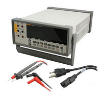
8808A 120V Fluke Electronics, 8808A 120V Datasheet - Page 97

8808A 120V
Manufacturer Part Number
8808A 120V
Description
DMM 5.5 RES RS-232 INTERFACE
Manufacturer
Fluke Electronics
Type
Digital (DMM)r
Specifications of 8808A 120V
Includes
Test Leads
Style
Bench
Display Digits
5.5
Display Type
VFD, Dual
Display Count
200000
Function
Voltage, Current, Resistance, Frequency
Functions, Extra
Continuity, dB, Diode Test
Features
Hold, Min/Max, RS-232 Port
Ranging
Auto/Manual
Response
True RMS
Lead Free Status / RoHS Status
Not applicable / RoHS non-compliant
Other names
614-1068
External Trigger
Thermal Voltages
Function
Meas.
Table A-5. Typical Measurement Intervals (in Seconds) for Dual Display Measurements
D
A
E
B
O
G
F
The external trigger can be used with or without settling delays, as shown in Table A-4.
(Refer to Table 4-3 for trigger types.) The amount of trigger delay varies depending on
differences between the primary and secondary displays, as described in the previous
section.
When external trigger is enabled, the meter determines the ranges for the primary and
secondary (if enabled) displays based on the input at that time. The meter is then ready to
begin measuring the input on the optimum range as soon as the trigger is received. If the
input changes so that either display autoranges after the trigger is received, the
autoranging response times (as shown in Table A-3) may be required before each
measurement result is displayed.
The rear panel trigger input is edge sensitive. A low to high pulse (above +3 V) will be
recognized as a trigger less than 3 ms.
Thermal voltages are the thermovoltaic potentials generated at the junction between
dissimilar metals. Thermal voltages typically occur at binding posts and can be greater
than 1 V. When making low-level dc measurements, thermal voltages can present an
additional source of error.
Thermal voltages can also cause problems in the low ohms ranges. Some low-value
resistors are constructed with dissimilar metals. Just handling such resistors can cause
thermal voltages large enough to introduce measurement errors.
Use the following techniques to reduce the effect of thermal voltages:
1. Use similar metals for connections wherever possible (e.g., copper-to-copper, gold-
2. Use tight connections.
3. Use clean connection (especially free of grease and dirt).
4. Use caution when handling the circuit under test.
5. Wait for the circuit to reach thermal equilibrium. (Thermal voltages are generated
to-gold, etc.).
only where there is a temperature gradient.)
Range
N/A
N/A
N/A
All
All
All
All
Slow
N/A
N/A
N/A
1.2
1.0
1.2
1.0
Med
0.85
0.85
N/A
N/A
N/A
1.0
1.0
Fast
N/A
N/A
N/A
0.9
0.8
0.9
0.8
Appendices
Applications
A
A-7


