8808A 120V Fluke Electronics, 8808A 120V Datasheet - Page 79
8808A 120V
Manufacturer Part Number
8808A 120V
Description
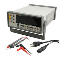
DMM 5.5 RES RS-232 INTERFACE
Manufacturer
Fluke Electronics
Type
Digital (DMM)r
Specifications of 8808A 120V
Includes
Test Leads
Style
Bench
Display Digits
5.5
Display Type
VFD, Dual
Display Count
200000
Function
Voltage, Current, Resistance, Frequency
Functions, Extra
Continuity, dB, Diode Test
Features
Hold, Min/Max, RS-232 Port
Ranging
Auto/Manual
Response
True RMS
Lead Free Status / RoHS Status
Not applicable / RoHS non-compliant
Other names
614-1068


Function Modifier Commands and Queries
DB
DBCLR
DBPOWER
DBREF <value>
DBREF?
HOLD
HOLDCLR
HOLDTHRESH
<threshold>
Command
Table 4-10 describes function modifier commands and queries. A function modifier
causes the Meter to modify the normal operation of a measurement function or to perform
an action on a measurement before displaying a reading. For example, the relative
modifier (REL) causes the Meter to display the difference between a measured value and
the relative base. The results of function modifier commands are shown in the primary
display only.
Table 4-10. Function Modifier Commands and Queries
Meter enters decibels modifier. Any reading shown in the primary display is in
decibels. An Execution Error is generated if the Meter is not in a volts ac
and/or dc function.
Meter exits the decibels modifier and displays readings in normal units. Also
clears dB power, REL, and MIN MAX modifiers
Meter enters dB Power modifier if the reference impedance is set to 2, 4, 8, or
16 ohms and a voltage function has been selected. Otherwise an Execution
Error is generated. In dB Power, readings shown in the primary display are in
Watts.
Meter returns a <value> shown in Table 4-10A. This value corresponds to the
reference impedance indicated.
Meter enters Touch Hold function. (See “Touch Hold Function (HOLD)” in
Chapter 3 for more information.) If HOLD is sent when the Meter is already in
Touch Hold, a reading is forced and shown on the display.
Meter exits Touch Hold and restores display to normal operation.
Sets HOLD measurement threshold to <threshold>.
<threshold> must be 1, 2, 3, or 4 (0.01%, 0.1%, 1% or 10%, respectively).
Any other value generates an Execution Error. See “Touch Hold Function
(HOLD)” in Chapter 3 for more information.
Set dB reference impedance to a <value> shown in Table 4-10A. This value
corresponds to the reference impedance (ohms) indicated. If <value> is not a
value in Table 4-10A, an Execution Error is generated.
Value
10
11
1
2
3
4
5
6
7
8
9
Table 4-10A. Reference Impedance Values
Ref Impedance
110
124
125
135
Operating the Meter Using the Computer Interface
16
50
75
93
2
4
8
Description
Value
12
13
14
15
16
17
18
19
20
21
Computer Interface Command Set
Ref Impedance
1000
1200
8000
150
250
300
500
600
800
900
4-19
4