8808A 120V Fluke Electronics, 8808A 120V Datasheet - Page 63
8808A 120V
Manufacturer Part Number
8808A 120V
Description
DMM 5.5 RES RS-232 INTERFACE
Manufacturer
Fluke Electronics
Type
Digital (DMM)r
Specifications of 8808A 120V
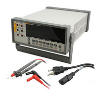
Includes
Test Leads
Style
Bench
Display Digits
5.5
Display Type
VFD, Dual
Display Count
200000
Function
Voltage, Current, Resistance, Frequency
Functions, Extra
Continuity, dB, Diode Test
Features
Hold, Min/Max, RS-232 Port
Ranging
Auto/Manual
Response
True RMS
Lead Free Status / RoHS Status
Not applicable / RoHS non-compliant
Other names
614-1068


Introduction
Local and Remote Operations
Computer Interfaces
Preparing the Meter for Operations via the RS-232 Interface
Setting Communication Parameters (RS-232)
This chapter describes how to set up, configure and operate the Meter via the RS-232
computer interface on the Meter’s rear panel. The Meter can be operated from a host (a
terminal, controller, PC, or computer) by sending commands to the Meter through its
computer interface.
An annotated sample program illustrating the use of the RS-232 computer interface is
provided at the end of this chapter. Refer to Chapter 3 for complete descriptions of all
Meter functions and features.
This chapter assumes that you are familiar with the basics of data communication and
RS-232 interface.
When the Meter is operated from a host, it is said to be operated remotely. When the
Meter is operated from its front panel, it is said to be operated locally.
Most operations that can be performed locally can also be performed remotely using the
computer interface. Some operations, like setting communications parameters for the RS-
232 interface operations, can only be performed from the front panel.
The Meter comes equipped with an RS-232 (serial) interface. Using the interface turns
the Meter into a fully programmable instrument that can be integrated into an automated
instrumentation system.
The RS-232 interface allows ASCII asynchronous serial communication between the
Meter and a host, serial printer or terminal.
Table 4-1 provides the RS-232 communication parameters factory settings. Setting RS-
232 communication parameters is only performed through the front panel.
In order for the Meter and host to communicate via the RS-232 interface, the
communication parameters of the Meter must match those of the host. If the
communications parameters of the host and Meter do not match, set the appropriate baud
rate and parity parameters as follows:
1. Press P to turn the Meter on.
2. Press Q then K. The baud rate currently selected is shown in the primary
3. Press U or V to scroll to the desired baud, and then press R to set the
4. Press U or V to scroll to the desired data bit (7 or 8) selection, then press
5. To select an Echo mode, press U or V to select On or OFF, and then press
display and baud is shown in the secondary display.
RS-232 baud rate.
R to set parity. Echo appears on the secondary display, and 0n or 0FF appears
on the primary display.
R to set the selected Echo state. When Echo is on, each command sent to the
Meter over the RS-232 interface is echoed to the host's display screen. When
Echo is off, commands are not echoed.
Operating the Meter Using the Computer Interface
Introduction
4
4-3