MPC8313E-RDB Freescale Semiconductor, MPC8313E-RDB Datasheet - Page 8
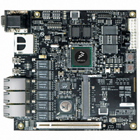
MPC8313E-RDB
Manufacturer Part Number
MPC8313E-RDB
Description
BOARD PROCESSOR
Manufacturer
Freescale Semiconductor
Series
PowerQUICC II™ PROr
Type
MCUr
Datasheets
1.MPC8313CZQAFFB.pdf
(100 pages)
2.MPC8313E-RDBB.pdf
(52 pages)
3.MPC8313E-RDBB.pdf
(2 pages)
Specifications of MPC8313E-RDB
Contents
Reference Design Board, Software and Documentation
Termination Type
SMD
Supply Voltage Max
1.05V
Tool / Board Applications
Wired Connectivity-LIN, CAN, Ethernet, USB
Mcu Supported Families
POWERQUICC II PRO
Rohs Compliant
Yes
Filter Terminals
SMD
Silicon Manufacturer
Freescale
Silicon Core Number
MPC83xx
Kit Application Type
Communication & Networking
Application Sub Type
Ethernet
Core Architecture
Power Architecture
Silicon Family Name
PowerQUICC II PRO
For Use With/related Products
MPC8313E
Lead Free Status / RoHS Status
Lead free / RoHS Compliant


Electrical Characteristics
amount of current listed in the Current Requirement column; this is the maximum current possible. Proper
device operation outside of these conditions is not guaranteed.
1
2
8
Core supply voltage
Internal core logic constant power
SerDes internal digital power
SerDes internal digital ground
SerDes I/O digital power
SerDes I/O digital ground
SerDes analog power for PLL
SerDes analog ground for PLL
Dedicated 3.3 V analog power for USB PLL
Dedicated 1.0 V analog power for USB PLL
Dedicated analog ground for USB PLL
Dedicated USB power for USB
Dedicated USB ground for USB bias circuit
Dedicated power for USB transceiver
Dedicated ground for USB transceiver
Analog power for e300 core APLL
Analog power for system APLL
DDR1 DRAM I/O voltage (333 MHz, 32-bit operation)
DDR2 DRAM I/O voltage (333 MHz, 32-bit operation)
Differential reference voltage for DDR controller
Standard I/O voltage
eTSEC2 IO supply
eTSEC1/USB DR IO supply
Supply for eLBC IOs
Analog and digital ground
Junction temperature
GV
direction.
Some GPIO pins may operate from a 2.5-V supply when configured for other functions.
DD
, NV
DD
, AV
DD
Characteristic
, and V
MPC8313E PowerQUICC
DD
bias
must track each other and must vary in the same direction—either in the positive or negative
Table 2. Recommended Operating Conditions
circuit
™
II Pro Processor Hardware Specifications, Rev. 3
USB_VDDA_BIAS
USB_VSSA_BIAS
USB_PLL_PWR3
USB_PLL_PWR1
USB_PLL_GND
XCOREV
USB_VDDA
XCOREV
USB_VSSA
XPADV
XPADV
SDAV
Symbol
SDAV
MV
AV
AV
LV
LV
GV
GV
NV
V
LV
V
V
DDC
T
DDB
DD
DDA
SS
DD1
DD2
REF
DD
DD
DD
DD
J
DD
SS
DD
SS
DD
SS
3.3 V ± 300 mV
2.5 V ± 125 mV/
2.5 V ± 125 mV/
Recommended
(0.49 × GV
3.3 V ± 300 mV
3.3 V ± 300 mV
3.3 V ± 300 mV
2.5 V ± 125 mV
1/2 DDR supply
3.3 V ± 300 mV
3.3 V ± 300 mV
3.3 V ± 300 mV
1.0 V ± 50 mV
1.0 V ± 50 mV
1.0 V ± 50 mV
1.0 V ± 50 mV
1.0 V ± 50 mV
1.0 V ± 50 mV
1.8 V ± 80 mV
0.51 × GV
0 to 105
Value
1.0
0.0
1.0
0.0
0.0
0.0
0.0
0.0
0.0
1
DD
DD
)
to
2
Freescale Semiconductor
Unit
°C
V
V
V
V
V
V
V
V
V
V
V
V
V
V
V
V
V
V
V
V
V
V
V
V
V
Requirement
Current
469 mA
377 mA
170 mA
2–3 mA
4–5 mA
2–3 mA
2–3 mA
131 mA
140 mA
2–3 mA
10 mA
10 mA
75 mA
74 mA
22 mA
44 mA
16 mA
—
—
—
—
—
—
—
—
—
Related parts for MPC8313E-RDB
Image
Part Number
Description
Manufacturer
Datasheet
Request
R

Part Number:
Description:
Mpc8313e Powerquicc Ii Pro Processor
Manufacturer:
Freescale Semiconductor, Inc
Datasheet:

Part Number:
Description:
BOARD CPU 8313E VER 2.1
Manufacturer:
Freescale Semiconductor
Datasheet:

Part Number:
Description:
BOARD CPU 8313E VER 2.2
Manufacturer:
Freescale Semiconductor
Datasheet:
Part Number:
Description:
Microprocessors - MPU 8313 REV2.2 PB ENC EXT
Manufacturer:
Freescale Semiconductor
Datasheet:
Part Number:
Description:
Microprocessors - MPU 8313 REV2.2 PB W/ENC
Manufacturer:
Freescale Semiconductor
Datasheet:
Part Number:
Description:
Microprocessors - MPU 8313 REV2.2 PB NO EN EXT
Manufacturer:
Freescale Semiconductor
Datasheet:
Part Number:
Description:
Microprocessors - MPU 8313 REV2.2 PB NO ENC
Manufacturer:
Freescale Semiconductor
Datasheet:
Part Number:
Description:
Manufacturer:
Freescale Semiconductor, Inc
Datasheet:
Part Number:
Description:
Manufacturer:
Freescale Semiconductor, Inc
Datasheet:
Part Number:
Description:
Manufacturer:
Freescale Semiconductor, Inc
Datasheet:
Part Number:
Description:
Manufacturer:
Freescale Semiconductor, Inc
Datasheet:
Part Number:
Description:
Manufacturer:
Freescale Semiconductor, Inc
Datasheet:
Part Number:
Description:
Manufacturer:
Freescale Semiconductor, Inc
Datasheet:
Part Number:
Description:
Manufacturer:
Freescale Semiconductor, Inc
Datasheet:
Part Number:
Description:
Manufacturer:
Freescale Semiconductor, Inc
Datasheet: