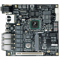
MPC8313E-RDB Freescale Semiconductor, MPC8313E-RDB Datasheet - Page 82

MPC8313E-RDB
Manufacturer Part Number
MPC8313E-RDB
Description
BOARD PROCESSOR
Manufacturer
Freescale Semiconductor
Series
PowerQUICC II™ PROr
Type
MCUr
Datasheets
1.MPC8313CZQAFFB.pdf
(100 pages)
2.MPC8313E-RDBB.pdf
(52 pages)
3.MPC8313E-RDBB.pdf
(2 pages)
Specifications of MPC8313E-RDB
Contents
Reference Design Board, Software and Documentation
Termination Type
SMD
Supply Voltage Max
1.05V
Tool / Board Applications
Wired Connectivity-LIN, CAN, Ethernet, USB
Mcu Supported Families
POWERQUICC II PRO
Rohs Compliant
Yes
Filter Terminals
SMD
Silicon Manufacturer
Freescale
Silicon Core Number
MPC83xx
Kit Application Type
Communication & Networking
Application Sub Type
Ethernet
Core Architecture
Power Architecture
Silicon Family Name
PowerQUICC II PRO
For Use With/related Products
MPC8313E
Lead Free Status / RoHS Status
Lead free / RoHS Compliant
Thermal
20.3
Table 69
reference frequencies, with RCWLR[LBCM] = 0 and RCWLR[DDRCM] =1, such that the LBC operates
with a frequency equal to the frequency of csb_clk and the DDR controller operates at twice the frequency
of csb_clk.
21 Thermal
This section describes the thermal specifications of the MPC8313E.
21.1
Table 70
82
Junction-to-ambient natural convection
Junction-to-ambient natural convection
Junction-to-ambient (@200 ft/min)
Junction-to-ambient (@200 ft/min)
Junction-to-board
1
2
3
4
5
6
PCI_CLK
CLK_IN/
System PLL multiplication factor.
System PLL VCO divider.
When considering operating frequencies, the valid core VCO operating range of 400–800 MHz must not be violated.
Due to erratum eTSEC40, csb_clk frequencies of less than 133 MHz do not support gigabit Ethernet data rates. The core
frequency must be 333 MHz for gigabit Ethernet operation. This erratum will be fixed in revision 2 silicon.
Frequency of USB PLL input reference.
USB reference clock must be supplied from a separate source as it must be 24 or 48 MHz, the USB reference must be
supplied from a separate external source using USB_CLK_IN.
SYS_
25.0
25.0
33.3
33.3
48.0
66.7
shows several possible frequency combinations that can be selected based on the indicated input
provides the package thermal characteristics for the 516, 27 × 27 mm TEPBGAII.
Example Clock Frequency Combinations
Thermal Characteristics
SPMF
Characteristic
6
5
5
4
3
2
1
VCOD
MPC8313E PowerQUICC
2
2
2
2
2
2
2
Table 70. Package Thermal Characteristics for TEPBGAII
VCO
600.0
500.0
666.0
532.8
576.0
533.4
3
( csb_clk )
Table 69. System Clock Frequencies
150.0
125.0
166.5
133.2
144.0
133.3
CSB
Four layer board (2s2p)
Four layer board (2s2p)
™
Single layer board (1s)
Single layer board (1s)
4
II Pro Processor Hardware Specifications, Rev. 3
(ddr_clk)
300.0
250.0
333.0
266.4
288.0
266.7
Board Type
DDR
—
62.5 31.25 15.6
66.6 33.3 16.7
66.7 33.34 16.7
—
—
—
/2
41.63 20.8
37.5 18.8
LBC(lbc_clk)
36
/4
18.0
Symbol
/8
R
R
R
R
R
θJMA
θJMA
θJA
θJA
θJB
Note 6
Note 6
Note 6
Note 6
Note
USB
48.0
ref
5
6
TEPBGA II
150.0
125.0
166.5
133.2
144.0
133.3
× 1
25
18
20
15
10
e300 Core(core_clk)
× 1.5
225
188
250
200
216
200
Freescale Semiconductor
300
250
333
266
288
267
°C/W
°C/W
°C/W
°C/W
°C/W
× 2
Unit
× 2.5
375
313
333
360
333
—
Notes
1, 2, 3
1, 2
1, 3
1, 3
375
400
400
4
× 3
—
—
—


