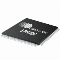
EP9302-CQZ Cirrus Logic Inc, EP9302-CQZ Datasheet - Page 734

EP9302-CQZ
Manufacturer Part Number
EP9302-CQZ
Description
IC ARM9 SOC PROCESSOR 208LQFP
Manufacturer
Cirrus Logic Inc
Series
EP9r
Datasheets
1.EP9307-CRZ.pdf
(824 pages)
2.EP9302-IQZ.pdf
(42 pages)
3.EP9302-IQZ.pdf
(4 pages)
4.EP9302-IQZ.pdf
(40 pages)
Specifications of EP9302-CQZ
Program Memory Type
ROMless
Package / Case
208-LQFP
Core Processor
ARM9
Core Size
16/32-Bit
Speed
200MHz
Connectivity
EBI/EMI, Ethernet, I²C, IrDA, SPI, UART/USART, USB
Peripherals
AC'97, DMA, I²:S, LED, MaverickKey, POR, PWM, WDT
Number Of I /o
19
Ram Size
32K x 8
Voltage - Supply (vcc/vdd)
1.65 V ~ 3.6 V
Data Converters
A/D 5x12b
Oscillator Type
External
Operating Temperature
0°C ~ 70°C
Processor Series
EP93xx
Core
ARM920T
Data Bus Width
32 bit
Data Ram Size
16 bit
Interface Type
USB, USART, SPI
Maximum Clock Frequency
200 MHz
Number Of Programmable I/os
37
Mounting Style
SMD/SMT
3rd Party Development Tools
MDK-ARM, RL-ARM, ULINK2
Development Tools By Supplier
EDB9302A-Z
Controller Family/series
(ARM9)
No. Of I/o's
19
Ram Memory Size
16MB
Cpu Speed
200MHz
No. Of Timers
4
Embedded Interface Type
AC97, I2S, SPI, UART, USB
Rohs Compliant
Yes
Lead Free Status / RoHS Status
Lead free / RoHS Compliant
For Use With
598-1132 - KIT DEVELOPMENT EP9302 ARM9
Eeprom Size
-
Program Memory Size
-
Lead Free Status / Rohs Status
Lead free / RoHS Compliant
Other names
598-1137
Available stocks
Company
Part Number
Manufacturer
Quantity
Price
Company:
Part Number:
EP9302-CQZ
Manufacturer:
Cirrus
Quantity:
3 295
Company:
Part Number:
EP9302-CQZ
Manufacturer:
ALTERA
Quantity:
672
Part Number:
EP9302-CQZ
Manufacturer:
CYPRESS/赛普拉斯
Quantity:
20 000
- EP9307-CRZ PDF datasheet
- EP9302-IQZ PDF datasheet #2
- EP9302-IQZ PDF datasheet #3
- EP9302-IQZ PDF datasheet #4
- Current page: 734 of 824
- Download datasheet (13Mb)
24
24-2
Pulse Width Modulator
EP93xx User’s Guide
24.2.1 PWM Programming Examples
24.2.1.1 Example
24.2.1.2 Static Programming (PWM is Not Running) Example
With those two counters specified, a fixed pulse is generated. The two channels are totally
independent. This is a DC-level PWM.
Either PWM channel can be utilized to create reoccurring pulses at the PWMx output pins.
Depending upon how a PWM is programmed, its output can vary from a continuous level
(100% duty-cycle), to a square wave (50% duty-cycle), to a narrow pulse approaching a 0%
duty-cycle. Both PWMs offer 16-bit resolution of the input clock signal.
The outputs of both PWM channels are programmed in terms of PWM input clock cycles.
Each PWM may be programmed statically (when it is halted) or dynamically (while it is
running). The output of either PWM may be programmed as normal or inverted. With the
exception of inversion, if a PWM is programmed statically, no change to the output will occur
until the PWM is enabled. If a PWM is reprogrammed while it is running (enabled), the output
is updated to the new programming (total period, total period asserted) at the beginning of the
next PWM cycle. The exception for inverted operation is explained below. Both PWMs are
reset to the halted condition.
The output of either PWM can be programmed for either normal or inverted operation.
Inversion affects the output pin when the PWM peripheral is halted and also when it is
running. Both outputs are reset to the normal (non-inverted) configuration, which places the
output pins in a LOW condition at reset. When the output is reprogrammed to be inverted (or
to be normal), the new programming does not become effective until the rising edge of the
PWM input clock signal.
The reference clock for PWM is XTALI.
To produce a PWM output of 100 kHz (10 μsec) and 20% duty cycle with a system clock of
66 MHz (15 nsec):
1. Calculate PWMxTermCnt = (66 MHz / 0.1 MHz) – 1 = 659 (decimal).
2. Calculate PWMxDutyCycle = (0.2 × (659 + 1)) – 1 = 131 (decimal).
Note: In the design, because of the use of clock gating on PCLK, the write enable and read
enable were altered to work correctly within the design.
Stop PWM
Wait for PWM to finish current cycle
Program TC value with 659 (decimal)
Program DC value with 131 (decimal)
Program PWM output to invert
Enable/Start PWM
Step
Copyright 2007 Cirrus Logic
Table 24-1. Static Programming Steps
PWMxEn
-----------------
PWMxTermCnt
PWMxDutyCycle
PWMxInvert
PWMxEn
Register
0x0000
0x0293
0x0083
0x0001
0x0001
Value
DS785UM1
Related parts for EP9302-CQZ
Image
Part Number
Description
Manufacturer
Datasheet
Request
R

Part Number:
Description:
IC ARM9 SOC PROCESSOR 208LQFP
Manufacturer:
Cirrus Logic Inc
Datasheet:

Part Number:
Description:
High Performance, Entry Level ARM9 SoC
Manufacturer:
Cirrus Logic Inc

Part Number:
Description:
MCU, MPU & DSP Development Tools Eval Bd Hgh-Prfrmnc ARM9 SOC Processor
Manufacturer:
Cirrus Logic Inc
Datasheet:

Part Number:
Description:
Development Kit
Manufacturer:
Cirrus Logic Inc
Datasheet:

Part Number:
Description:
Development Kit
Manufacturer:
Cirrus Logic Inc
Datasheet:

Part Number:
Description:
High-efficiency PFC + Fluorescent Lamp Driver Reference Design
Manufacturer:
Cirrus Logic Inc
Datasheet:

Part Number:
Description:
Development Kit
Manufacturer:
Cirrus Logic Inc
Datasheet:

Part Number:
Description:
Development Kit
Manufacturer:
Cirrus Logic Inc
Datasheet:

Part Number:
Description:
Development Kit
Manufacturer:
Cirrus Logic Inc
Datasheet:

Part Number:
Description:
Development Kit
Manufacturer:
Cirrus Logic Inc
Datasheet:

Part Number:
Description:
Development Kit
Manufacturer:
Cirrus Logic Inc
Datasheet:

Part Number:
Description:
Ref Bd For Speakerbar MSA & DSP Products
Manufacturer:
Cirrus Logic Inc


