R5F363AENFA#U0 Renesas Electronics America, R5F363AENFA#U0 Datasheet - Page 878
R5F363AENFA#U0
Manufacturer Part Number
R5F363AENFA#U0
Description
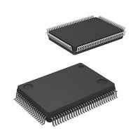
MCU 4KB FLASH 256/16K 100-QFP
Manufacturer
Renesas Electronics America
Series
M16C/60/63r
Specifications of R5F363AENFA#U0
Core Processor
M16C/60
Core Size
16/32-Bit
Speed
20MHz
Connectivity
EBI/EMI, I²C, SIO, UART/USART
Peripherals
DMA, LVD, POR, PWM, WDT
Number Of I /o
85
Program Memory Size
256KB (256K x 8)
Program Memory Type
FLASH
Ram Size
20K x 8
Voltage - Supply (vcc/vdd)
1.8 V ~ 5.5 V
Data Converters
A/D 26x10b; D/A 2x8b
Oscillator Type
Internal
Operating Temperature
-20°C ~ 85°C
Package / Case
100-QFP
Lead Free Status / RoHS Status
Lead free / RoHS Compliant
Eeprom Size
-
Available stocks
Company
Part Number
Manufacturer
Quantity
Price


Rev.
Revision History
Date
Page
506
519
521
535
538
550
556
560
570
575
588
592
594
597
603
603
607
608
627
628
635
636
637
646
647
649
652
653
668
668
668
669
669
682
-
Table 23.15 “Example Bit Rates and Settings” 24 MHz value deleted
23.3.3.5 “SDA Output” 2 to 8 → 1 to 8 UiBRG count source clock cycles
Table 23.22 “Special Mode 2 Specifications” partially modified
23.5.1.3 “CLKi Output” added
24. “Serial Interface SI/O3 and SI/O4” S32C2 → S34C2
Table 24.1 “SI/O3 and SI/O4 Specifications” Transmit/receive clocks
partially added
Figure 24.7 “Timing Chart for Setting SOUTi Initial Value and How to Set It”
partially modified
Table 25.4 “Register Configuration” S11’s reset value modified
25.2.4 “I2C0 Address Register i (S0Di) (i = 0 to 2)” partially modified
Figure 25.4 “Interrupt Request Generation Timing in Receive Mode”
partially modified
Table 25.10 “Functions Enabled by Writing to the S10 Register” partially
added
Figure 25.11 “Start Condition Overlap Protect Function Enable Period”
partially modified
Table 25.15 “Recommended Value of Bits SSC4 to SSC0 in Standard
Clock Mode” 4.125 μs → 3.3 μs
Figure 25.16 “Timeout Detection Timing” partially modified
25.3.10.3 “Master Reception” partially modified
25.5.2.4 “S3D0 Register” partially added
25.5.2.6 “S10 Register” partially modified
26.2.1 “CEC Function Control Register 1 (CECC1)” partially modified
26.2.2 “CEC Function Control Register 2 (CECC2)” partially deleted
Figure 26.10 “Reception Example (Change from Error Low Pulse Output
Disabled to Enabled When an Error Occurs)” partially modified
Figure 26.12 “Falling Timing of Transmit Signal” 000b → 00b
26.5.2 “Low Level Period of ACK Input/Output” deleted
Table 27.1 “A/D Converter Specifications” partially modified
Figure 27.1 “A/D Converter Block Diagram” partially modified
27.2.7 “A/D Control Register 1 (ADCON1)” partially modified
Figure 27.3 “A/D Conversion Timing” 2.5 φAD → 25 φAD
Figure 27.5 “A/D conversion Start Timing When External Trigger Input”
added
Figure 27.8 and Figure 27.9 A/D Open-Circuit Detection Characteristics
(Standard Characteristics) added
27.3.7 “Voltage Multiplying Function” partially added
27.7.1 “Analog Input Pin” partially deleted
27.7.2 "φA/D frequency" deleted
27.7.2 “Pin Configuration” partially modified
27.7.10 “Repeat Mode, Repeat Sweep Mode 0, and Repeat Sweep Mode
1” deleted
27.7.7 “A/D Open-Circuit Detection Assist Function” partially deleted
30.2 “Memory Map” partially modified
M16C/63 Group Hardware Manual
C - 4
Description
Summary
Related parts for R5F363AENFA#U0
Image
Part Number
Description
Manufacturer
Datasheet
Request
R

Part Number:
Description:
KIT STARTER FOR M16C/29
Manufacturer:
Renesas Electronics America
Datasheet:

Part Number:
Description:
KIT STARTER FOR R8C/2D
Manufacturer:
Renesas Electronics America
Datasheet:

Part Number:
Description:
R0K33062P STARTER KIT
Manufacturer:
Renesas Electronics America
Datasheet:

Part Number:
Description:
KIT STARTER FOR R8C/23 E8A
Manufacturer:
Renesas Electronics America
Datasheet:

Part Number:
Description:
KIT STARTER FOR R8C/25
Manufacturer:
Renesas Electronics America
Datasheet:

Part Number:
Description:
KIT STARTER H8S2456 SHARPE DSPLY
Manufacturer:
Renesas Electronics America
Datasheet:

Part Number:
Description:
KIT STARTER FOR R8C38C
Manufacturer:
Renesas Electronics America
Datasheet:

Part Number:
Description:
KIT STARTER FOR R8C35C
Manufacturer:
Renesas Electronics America
Datasheet:

Part Number:
Description:
KIT STARTER FOR R8CL3AC+LCD APPS
Manufacturer:
Renesas Electronics America
Datasheet:
Part Number:
Description:
KIT STARTER FOR RX610
Manufacturer:
Renesas Electronics America
Datasheet:

Part Number:
Description:
KIT STARTER FOR R32C/118
Manufacturer:
Renesas Electronics America
Datasheet:

Part Number:
Description:
KIT DEV RSK-R8C/26-29
Manufacturer:
Renesas Electronics America
Datasheet:

Part Number:
Description:
KIT STARTER FOR SH7124
Manufacturer:
Renesas Electronics America
Datasheet:

Part Number:
Description:
KIT STARTER FOR H8SX/1622
Manufacturer:
Renesas Electronics America
Datasheet:

Part Number:
Description:
KIT DEV FOR SH7203
Manufacturer:
Renesas Electronics America
Datasheet: