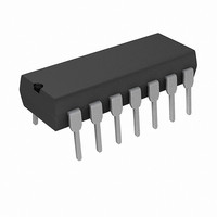
PIC16F1824-I/P Microchip Technology, PIC16F1824-I/P Datasheet - Page 18

PIC16F1824-I/P
Manufacturer Part Number
PIC16F1824-I/P
Description
IC PIC MCU 8BIT 14KB FLSH 14PDIP
Manufacturer
Microchip Technology
Series
PIC® XLP™ 16Fr
Datasheets
1.PIC16F722-ISS.pdf
(8 pages)
2.PIC16F1824-ISL.pdf
(2 pages)
3.PIC16F1824-ISL.pdf
(419 pages)
4.PIC16F1824-ISL.pdf
(10 pages)
5.PIC16F1824-IP.pdf
(10 pages)
Specifications of PIC16F1824-I/P
Core Processor
PIC
Core Size
8-Bit
Speed
32MHz
Connectivity
I²C, SPI, UART/USART
Peripherals
Brown-out Detect/Reset, POR, PWM, WDT
Number Of I /o
11
Program Memory Size
7KB (4K x 14)
Program Memory Type
FLASH
Eeprom Size
256 x 8
Ram Size
256 x 8
Voltage - Supply (vcc/vdd)
1.8 V ~ 5.5 V
Data Converters
A/D 8x10b
Oscillator Type
Internal
Operating Temperature
-40°C ~ 85°C
Package / Case
14-DIP (0.300", 7.62mm)
Processor Series
PIC16F
Core
PIC
3rd Party Development Tools
52715-96, 52716-328, 52717-734
Development Tools By Supplier
PG164130, DV164035, DV244005, DV164005
Lead Free Status / RoHS Status
Lead free / RoHS Compliant
Lead Free Status / RoHS Status
Lead free / RoHS Compliant, Lead free / RoHS Compliant
- PIC16F722-ISS PDF datasheet
- PIC16F1824-ISL PDF datasheet #2
- PIC16F1824-ISL PDF datasheet #3
- PIC16F1824-ISL PDF datasheet #4
- PIC16F1824-IP PDF datasheet #5
- Current page: 18 of 419
- Download datasheet (4Mb)
PIC16(L)F1824/1828
TABLE 1-3:
DS41419B-page 18
RA0/AN0/CPS0/C1IN+/V
DACOUT/ICSPDAT/ICDDAT
RA1/AN1/CPS1/C12IN0-/V
SRI/ICSPCLK/ICDCLK
RA2/AN2/CPS2/T0CKI/INT/
C1OUT/SRQ/CCP3/FLT0
RA3/T1G
RA4/AN3/CPS3/OSC2/
CLKOUT/T1OSO/CLKR/P2B
T1G
Legend: AN = Analog input or output CMOS = CMOS compatible input or output
Note 1: Pin functions can be moved using the APFCONO and APFCON1 registers
(1,2)
2: Default function location.
(1)
TTL = TTL compatible input
HV = High Voltage
/V
Name
PP
/MCLR
PIC16F/LF1828 PINOUT DESCRIPTION
REF
REF
-/
(1)
+/
/
ICSPCLK
Function
DACOUT
ICSPDAT
CLKOUT
C12IN0-
ICDDAT
ICDCLK
C1OUT
T1OSO
C1IN+
V
T0CKI
MCLR
CPS0
CPS1
CPS2
CCP3
CPS3
OSC2
CLKR
V
SRQ
FLT0
RA0
AN0
RA1
AN1
RA2
AN2
RA3
T1G
RA4
AN3
P2B
T1G
V
REF
SRI
INT
REF
PP
ST
XTAL = Crystal
+
-
Input
XTAL
Type
= Schmitt Trigger input with CMOS levels I
TTL
TTL
TTL
TTL
TTL
AN
AN
AN
AN
ST
ST
AN
AN
AN
AN
ST
ST
ST
AN
AN
ST
ST
ST
ST
ST
HV
ST
AN
AN
ST
—
—
—
—
—
—
—
Preliminary
Output
CMOS General purpose I/O.
CMOS ICSP™ Data I/O.
CMOS In-Circuit Data I/O.
CMOS General purpose I/O.
CMOS General purpose I/O.
CMOS Comparator C1 output.
CMOS SR latch non-inverting output.
CMOS Capture/Compare/PWM 3.
CMOS General purpose I/O.
CMOS Comparator C2 output.
CMOS F
CMOS Clock Reference output.
CMOS PWM output.
XTAL
Type
AN
—
—
—
—
—
—
—
—
—
—
—
—
—
—
—
—
—
—
—
—
—
—
—
A/D Channel 0 input.
Capacitive sensing input 0.
Comparator C1 positive input.
A/D and DAC Negative Voltage Reference input.
Digital-to-Analog Converter output.
A/D Channel 1 input.
Capacitive sensing input 1.
Comparator C1 or C2 negative input.
A/D and DAC Positive Voltage Reference input.
SR latch input.
Serial Programming Clock.
In-Circuit Debug Clock.
A/D Channel 2 input.
Capacitive sensing input 2.
Timer0 clock input.
External interrupt.
ECCP Auto-Shutdown Fault input.
General purpose input.
Timer1 Gate input.
Programming voltage.
Master Clear with internal pull-up.
A/D Channel 3 input.
Capacitive sensing input 3.
Timer1 oscillator connection.
Timer1 Gate input.
OSC
/4 output.
(Register 12-1
Description
OD
2
C™ = Schmitt Trigger input with I
2010 Microchip Technology Inc.
= Open Drain
and
levels
Register
12-2).
2
C
Related parts for PIC16F1824-I/P
Image
Part Number
Description
Manufacturer
Datasheet
Request
R

Part Number:
Description:
IC, 8BIT MCU, PIC16F, 32MHZ, SOIC-18
Manufacturer:
Microchip Technology
Datasheet:

Part Number:
Description:
IC, 8BIT MCU, PIC16F, 32MHZ, SSOP-20
Manufacturer:
Microchip Technology
Datasheet:

Part Number:
Description:
IC, 8BIT MCU, PIC16F, 32MHZ, DIP-18
Manufacturer:
Microchip Technology
Datasheet:

Part Number:
Description:
IC, 8BIT MCU, PIC16F, 32MHZ, QFN-28
Manufacturer:
Microchip Technology
Datasheet:

Part Number:
Description:
IC, 8BIT MCU, PIC16F, 32MHZ, QFN-28
Manufacturer:
Microchip Technology
Datasheet:

Part Number:
Description:
IC, 8BIT MCU, PIC16F, 32MHZ, QFN-28
Manufacturer:
Microchip Technology
Datasheet:

Part Number:
Description:
IC, 8BIT MCU, PIC16F, 32MHZ, SSOP-20
Manufacturer:
Microchip Technology
Datasheet:

Part Number:
Description:
IC, 8BIT MCU, PIC16F, 20MHZ, DIP-40
Manufacturer:
Microchip Technology
Datasheet:

Part Number:
Description:
IC, 8BIT MCU, PIC16F, 32MHZ, QFN-28
Manufacturer:
Microchip Technology
Datasheet:

Part Number:
Description:
IC, 8BIT MCU, PIC16F, 20MHZ, MQFP-44
Manufacturer:
Microchip Technology
Datasheet:

Part Number:
Description:
IC, 8BIT MCU, PIC16F, 20MHZ, QFN-20
Manufacturer:
Microchip Technology
Datasheet:

Part Number:
Description:
IC, 8BIT MCU, PIC16F, 32MHZ, QFN-28
Manufacturer:
Microchip Technology
Datasheet:

Part Number:
Description:
MCU 14KB FLASH 768B RAM 64-TQFP
Manufacturer:
Microchip Technology
Datasheet:

Part Number:
Description:
7 KB Flash, 384 Bytes RAM, 32 MHz Int. Osc, 16 I/0, Enhanced Mid Range Core, Low
Manufacturer:
Microchip Technology

Part Number:
Description:
14KB Flash, 512B RAM, 256B EEPROM, LCD, 1.8-5.5V 40 UQFN 5x5x0.5mm TUBE
Manufacturer:
Microchip Technology
Datasheet:


