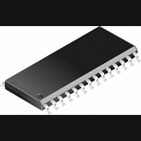
PIC14000-04I/SS Microchip Technology, PIC14000-04I/SS Datasheet - Page 10

PIC14000-04I/SS
Manufacturer Part Number
PIC14000-04I/SS
Description
IC, 8BIT MCU, PIC14, 4MHZ, SSOP-28
Manufacturer
Microchip Technology
Datasheet
1.PIC14000-04SO.pdf
(153 pages)
Specifications of PIC14000-04I/SS
Controller Family/series
PIC14
No. Of I/o's
22
Ram Memory Size
192Byte
Cpu Speed
4MHz
No. Of Timers
2
Interface
I2C
Digital Ic Case Style
SSOP
Core Size
8 Bit
Program Memory Size
4096 X 14
Embedded Interface Type
I2C
Rohs Compliant
Yes
Processor Series
PIC14000
Core
PIC
Data Bus Width
8 bit
Program Memory Type
EPROM
Data Ram Size
192 B
Interface Type
SPI, UART
Maximum Clock Frequency
20 MHz
Number Of Programmable I/os
22
Number Of Timers
1
Operating Supply Voltage
2.7 V to 6 V
Maximum Operating Temperature
+ 85 C
Mounting Style
SMD/SMT
Package / Case
SSOP-28
Development Tools By Supplier
ICE2000
Minimum Operating Temperature
- 40 C
On-chip Adc
14 bit
Lead Free Status / RoHS Status
Lead free / RoHS Compliant
- Current page: 10 of 153
- Download datasheet (767Kb)
PIC14000
TABLE 3-1:
Legend:
DS40122B-page 10
RD3/REFB
RD4/AN4
RD5/AN5
RD6/AN6
RD7/AN7
VREG
OSC1/PBTN
OSC2/
CLKOUT
MCLR/VPP
V
V
DD
SS
Pin Name
Type:
TTL
CMOS
ST
SM
OD
NPU
PU
No-P diode
AN
PIN DESCRIPTIONS (CONTINUED)
Pin
No.
26
25
24
23
10
14
20
3
8
7
9
Definition:
TTL-compatible input
CMOS-compatible input or output
Schmitt Trigger input, with CMOS levels
SMBus compatible input
Open-drain output. An external pull-up resistor is required if this pin is used as an output.
N-channel pull-up. This pin will pull-up to approximately V
Weak internal pull-up (10K-50K ohms)
No P-diode to V
Analog input or output
I/O-PU
I/PWR
PWR
GND
I-PU
I/O
I/O
I/O
I/O
I/O
O
O
AN/ST
AN/ST
AN/ST
AN/ST
AN/ST
DD
ST
ST
—
—
Input Output
. This pin may be pulled above the supply rail (to 6.0V maximum).
Pin Type
CMOS
CMOS
CMOS
CMOS
CMOS
AN
—
CMOS
Preliminary
General purpose I/O or programmable reference B
output.
Analog input channel 4. This pin can also serve as a
GPIO.
Analog input channel 5. This pin can connect to a level
shift network. If enabled, a +0.5V offset is added to the
input voltage. This pin can also serve as a GPIO.
Analog input channel 6. This pin can also serve as a
GPIO.
Analog input channel 7. This pin can also serve as a
GPIO.
This pin is an output to control the gate of an external
N-FET for voltage regulation.
IN Mode: Input with weak pull-up resistor, can be used to
generate an interrupt.
HS Mode: External oscillator input.
IN Mode: General purpose output.
HS Mode: External oscillator/clock output.
Master clear (reset) input / programming voltage input.
This pin is an active low reset to the device.
Positive supply connection
Return supply connection
DD
- 1.0V when outputting a logical ‘1’.
Description
1996 Microchip Technology Inc.
Related parts for PIC14000-04I/SS
Image
Part Number
Description
Manufacturer
Datasheet
Request
R

Part Number:
Description:
IC MCU OTP 4KX14 A/D 28SOIC
Manufacturer:
Microchip Technology
Datasheet:

Part Number:
Description:
IC MCU OTP 4KX14 A/D 28SSOP
Manufacturer:
Microchip Technology
Datasheet:

Part Number:
Description:
IC MCU OTP 4KX14 A/D 28SOIC
Manufacturer:
Microchip Technology
Datasheet:

Part Number:
Description:
IC MCU OTP 4KX14 A/D 28DIP
Manufacturer:
Microchip Technology
Datasheet:

Part Number:
Description:
IC MCU OTP 4KX14 A/D 28SSOP
Manufacturer:
Microchip Technology
Datasheet:

Part Number:
Description:
IC MCU OTP 4KX14 A/D 28CDIP
Manufacturer:
Microchip Technology
Datasheet:

Part Number:
Description:
IC MCU OTP 4KX14 A/D 28DIP
Manufacturer:
Microchip Technology
Datasheet:

Part Number:
Description:
IC MCU OTP 4KX14 A/D 28SOIC
Manufacturer:
Microchip Technology
Datasheet:

Part Number:
Description:
IC MCU OTP 4KX14 A/D 28DIP
Manufacturer:
Microchip Technology
Datasheet:

Part Number:
Description:
IC MCU OTP 4KX14 A/D 28DIP
Manufacturer:
Microchip Technology
Datasheet:

Part Number:
Description:
IC MCU OTP 4KX14 A/D 28SOIC
Manufacturer:
Microchip Technology
Datasheet:

Part Number:
Description:
IC MCU OTP 4KX14 A/D 28SSOP
Manufacturer:
Microchip Technology
Datasheet:

Part Number:
Description:
28-Pin Programmable Mixed Signal Controller
Manufacturer:
Microchip Technology
Datasheet:


