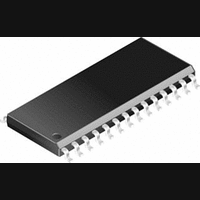
PIC14000-04I/SS Microchip Technology, PIC14000-04I/SS Datasheet - Page 13

PIC14000-04I/SS
Manufacturer Part Number
PIC14000-04I/SS
Description
IC, 8BIT MCU, PIC14, 4MHZ, SSOP-28
Manufacturer
Microchip Technology
Datasheet
1.PIC14000-04SO.pdf
(153 pages)
Specifications of PIC14000-04I/SS
Controller Family/series
PIC14
No. Of I/o's
22
Ram Memory Size
192Byte
Cpu Speed
4MHz
No. Of Timers
2
Interface
I2C
Digital Ic Case Style
SSOP
Core Size
8 Bit
Program Memory Size
4096 X 14
Embedded Interface Type
I2C
Rohs Compliant
Yes
Processor Series
PIC14000
Core
PIC
Data Bus Width
8 bit
Program Memory Type
EPROM
Data Ram Size
192 B
Interface Type
SPI, UART
Maximum Clock Frequency
20 MHz
Number Of Programmable I/os
22
Number Of Timers
1
Operating Supply Voltage
2.7 V to 6 V
Maximum Operating Temperature
+ 85 C
Mounting Style
SMD/SMT
Package / Case
SSOP-28
Development Tools By Supplier
ICE2000
Minimum Operating Temperature
- 40 C
On-chip Adc
14 bit
Lead Free Status / RoHS Status
Lead free / RoHS Compliant
- Current page: 13 of 153
- Download datasheet (767Kb)
4.0
4.1
The PIC14000 has a 13-bit program counter capable of
addressing an 8K x 14 program memory space. Only
the first 4K x 14 (0000-0FFFh) are physically imple-
mented. Accessing a location above the physically
implemented address will cause a wraparound. The
reset vector is at 0000h and the interrupt vector is at
0004h (Figure 4-1).
The 4096 words of Program Memory space are divided
into:
• Address Vectors (addr 0000h-0004h)
• Program Memory Page 0 (addr 0005h-07FFH)
• Program Memory Page 1 (addr 0800h-0FBFh)
• Calibration Space (64 words, addr 0FC0h-0FFFh)
Program code may reside in Page 0 and Page 1.
FIGURE 4-1:
1996 Microchip Technology Inc.
RETFIE, RETLW
CALL, RETURN,
MEMORY ORGANIZATION
Program Memory Organization
Calibration Space
Memory (Page 0)
Memory (Page 1)
On-chip Program
On-chip Program
Interrupt Vector
PIC14000 PROGRAM
MEMORY MAP AND STACK
Stack Level 1
Stack Level 8
Reset Vector
(64 words)
PC<12:0>
•
•
•
•
•
This document was created with FrameMaker 4 0 4
0004h
0005h
07FFh
0800h
0FBFh
0FC0h
0FFFh
1000h
20FFh
13
0000h
Preliminary
4.1.1
The calibration space is not used for instructions. This
section stores constants and factors for the arithmetic
calculations to calibrate the analog measurements.
TABLE 4-1:
** Microchip modified IEEE754 32-bit floating point format.
0FC0h-0FC3h
0FC4h-0FC7h
0FC8h-0FCBh
0FCCh-0FCFh
0FD0h
0FD2h
* Refer to AN621 for details.
Refer to application note AN575 for details.
Address
CALIBRATION SPACE
Slope
reference
ratio
Bandgap
reference
voltage
Tempera-
ture sensor
voltage
Tempera-
ture sensor
coefficient
Internal
oscillator
frequency
multiplier
WDT
time-out
Parameter Symbol
CALIBRATION DATA
OVERVIEW*
V
PIC14000
T
K
F
K
THERM
K
OSC
WDT
REF
BG
TC
DS40122B-page 13
Celsius
degree
Units
Volts/
Volts
Volts
N/A
N/A
ms
32-bit
floating
point **
32-bit
floating
point
32-bit
floating
point
32-bit
floating
point
Format
byte
byte
Related parts for PIC14000-04I/SS
Image
Part Number
Description
Manufacturer
Datasheet
Request
R

Part Number:
Description:
IC MCU OTP 4KX14 A/D 28SOIC
Manufacturer:
Microchip Technology
Datasheet:

Part Number:
Description:
IC MCU OTP 4KX14 A/D 28SSOP
Manufacturer:
Microchip Technology
Datasheet:

Part Number:
Description:
IC MCU OTP 4KX14 A/D 28SOIC
Manufacturer:
Microchip Technology
Datasheet:

Part Number:
Description:
IC MCU OTP 4KX14 A/D 28DIP
Manufacturer:
Microchip Technology
Datasheet:

Part Number:
Description:
IC MCU OTP 4KX14 A/D 28SSOP
Manufacturer:
Microchip Technology
Datasheet:

Part Number:
Description:
IC MCU OTP 4KX14 A/D 28CDIP
Manufacturer:
Microchip Technology
Datasheet:

Part Number:
Description:
IC MCU OTP 4KX14 A/D 28DIP
Manufacturer:
Microchip Technology
Datasheet:

Part Number:
Description:
IC MCU OTP 4KX14 A/D 28SOIC
Manufacturer:
Microchip Technology
Datasheet:

Part Number:
Description:
IC MCU OTP 4KX14 A/D 28DIP
Manufacturer:
Microchip Technology
Datasheet:

Part Number:
Description:
IC MCU OTP 4KX14 A/D 28DIP
Manufacturer:
Microchip Technology
Datasheet:

Part Number:
Description:
IC MCU OTP 4KX14 A/D 28SOIC
Manufacturer:
Microchip Technology
Datasheet:

Part Number:
Description:
IC MCU OTP 4KX14 A/D 28SSOP
Manufacturer:
Microchip Technology
Datasheet:

Part Number:
Description:
28-Pin Programmable Mixed Signal Controller
Manufacturer:
Microchip Technology
Datasheet:


