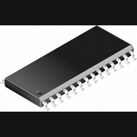
PIC14000-04I/SS Microchip Technology, PIC14000-04I/SS Datasheet - Page 85

PIC14000-04I/SS
Manufacturer Part Number
PIC14000-04I/SS
Description
IC, 8BIT MCU, PIC14, 4MHZ, SSOP-28
Manufacturer
Microchip Technology
Datasheet
1.PIC14000-04SO.pdf
(153 pages)
Specifications of PIC14000-04I/SS
Controller Family/series
PIC14
No. Of I/o's
22
Ram Memory Size
192Byte
Cpu Speed
4MHz
No. Of Timers
2
Interface
I2C
Digital Ic Case Style
SSOP
Core Size
8 Bit
Program Memory Size
4096 X 14
Embedded Interface Type
I2C
Rohs Compliant
Yes
Processor Series
PIC14000
Core
PIC
Data Bus Width
8 bit
Program Memory Type
EPROM
Data Ram Size
192 B
Interface Type
SPI, UART
Maximum Clock Frequency
20 MHz
Number Of Programmable I/os
22
Number Of Timers
1
Operating Supply Voltage
2.7 V to 6 V
Maximum Operating Temperature
+ 85 C
Mounting Style
SMD/SMT
Package / Case
SSOP-28
Development Tools By Supplier
ICE2000
Minimum Operating Temperature
- 40 C
On-chip Adc
14 bit
Lead Free Status / RoHS Status
Lead free / RoHS Compliant
- Current page: 85 of 153
- Download datasheet (767Kb)
10.7
The watchdog timer is realized as a free running
on-chip RC oscillator which does not require any
external components. This RC oscillator is separate
from the IN oscillator used to generate the CPU and
A/D clocks. That means that the WDT will run even if
the clock has been stopped, for example, by execution
of a SLEEP instruction. Refer to Section 10.8.1 for more
information.
During normal operation, a WDT time-out generates a
device RESET. If the device is in SLEEP mode, a WDT
time-out causes the device to wake-up and continue
with normal operation.
FIGURE 10-11: WATCHDOG TIMER BLOCK DIAGRAM (WITH TIMER0)
1996 Microchip Technology Inc.
RC3/T0CKI
pin
HIBERNATE
Watchdog Timer (WDT)
Oscillator
Enable
18 mS
Timer
Local
T0SE
F
WDT
Enable Bit
OSC
/4
Watchdog Timer
T0CS
0
1
PSA
0
1
Note: T0CS, T0SE, PSA, PS2:PS0 correspond to (OPTION<5:0>).
Preliminary
8-bit Counter
Timer0
8-to-1 MUX
1
8
0
Time-out
The
programming the configuration bit WDTE as a ‘0’. Its
oscillator can be shut down to conserve battery power
by
Section 10.8.3 for more information on HIBERNATE
mode.
A block diagram of the watchdog timer is shown in
Figure 10-11. It should be noted that a RESET
generated by the WDT time-out does not drive MCLR
low.
PSA
WDT
1
0
CAUTION: Beware of disabling WDT if software
PSout
entering
WDT
(2 cycle delay)
PSA
Sync with
3
Internal
Postscaler
Prescaler/
clocks
can
routines require exiting based on WDT
reset. For example, the MCU will not
exit HIBERNATE mode based on WDT
reset.
PS2:PS0
HIBERNATE
be
PSout
permanently
PIC14000
Data bus
TMR0
Mode.
Set T0IF
Interrupt on
Overflow
DS40122B-page 85
8
disabled
Refer
by
to
Related parts for PIC14000-04I/SS
Image
Part Number
Description
Manufacturer
Datasheet
Request
R

Part Number:
Description:
IC MCU OTP 4KX14 A/D 28SOIC
Manufacturer:
Microchip Technology
Datasheet:

Part Number:
Description:
IC MCU OTP 4KX14 A/D 28SSOP
Manufacturer:
Microchip Technology
Datasheet:

Part Number:
Description:
IC MCU OTP 4KX14 A/D 28SOIC
Manufacturer:
Microchip Technology
Datasheet:

Part Number:
Description:
IC MCU OTP 4KX14 A/D 28DIP
Manufacturer:
Microchip Technology
Datasheet:

Part Number:
Description:
IC MCU OTP 4KX14 A/D 28SSOP
Manufacturer:
Microchip Technology
Datasheet:

Part Number:
Description:
IC MCU OTP 4KX14 A/D 28CDIP
Manufacturer:
Microchip Technology
Datasheet:

Part Number:
Description:
IC MCU OTP 4KX14 A/D 28DIP
Manufacturer:
Microchip Technology
Datasheet:

Part Number:
Description:
IC MCU OTP 4KX14 A/D 28SOIC
Manufacturer:
Microchip Technology
Datasheet:

Part Number:
Description:
IC MCU OTP 4KX14 A/D 28DIP
Manufacturer:
Microchip Technology
Datasheet:

Part Number:
Description:
IC MCU OTP 4KX14 A/D 28DIP
Manufacturer:
Microchip Technology
Datasheet:

Part Number:
Description:
IC MCU OTP 4KX14 A/D 28SOIC
Manufacturer:
Microchip Technology
Datasheet:

Part Number:
Description:
IC MCU OTP 4KX14 A/D 28SSOP
Manufacturer:
Microchip Technology
Datasheet:

Part Number:
Description:
28-Pin Programmable Mixed Signal Controller
Manufacturer:
Microchip Technology
Datasheet:


