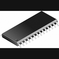
PIC14000-04I/SS Microchip Technology, PIC14000-04I/SS Datasheet - Page 108

PIC14000-04I/SS
Manufacturer Part Number
PIC14000-04I/SS
Description
IC, 8BIT MCU, PIC14, 4MHZ, SSOP-28
Manufacturer
Microchip Technology
Datasheet
1.PIC14000-04SO.pdf
(153 pages)
Specifications of PIC14000-04I/SS
Controller Family/series
PIC14
No. Of I/o's
22
Ram Memory Size
192Byte
Cpu Speed
4MHz
No. Of Timers
2
Interface
I2C
Digital Ic Case Style
SSOP
Core Size
8 Bit
Program Memory Size
4096 X 14
Embedded Interface Type
I2C
Rohs Compliant
Yes
Processor Series
PIC14000
Core
PIC
Data Bus Width
8 bit
Program Memory Type
EPROM
Data Ram Size
192 B
Interface Type
SPI, UART
Maximum Clock Frequency
20 MHz
Number Of Programmable I/os
22
Number Of Timers
1
Operating Supply Voltage
2.7 V to 6 V
Maximum Operating Temperature
+ 85 C
Mounting Style
SMD/SMT
Package / Case
SSOP-28
Development Tools By Supplier
ICE2000
Minimum Operating Temperature
- 40 C
On-chip Adc
14 bit
Lead Free Status / RoHS Status
Lead free / RoHS Compliant
PIC14000
13.1
Note 1: This is the limit to which V
DS40122B-page 108
Supply Voltage
RAM Data Retention
Voltage (Note 1)
V
guarantee Power-On Reset
V
Power-On Reset
Operating Current in SLEEP Mode (Note 2)
During A/D conversion:
all analog on and internal
oscillator active
Comparator interrupt enabled:
level-shift, programmable
reference, and comparator active
All analog off, WDT on (Note 5)
All analog off, WDT off
(Hibernate mode) (Note 5)
Operating Supply Current (Note 2, 4)
Internal oscillator mode
HS oscillator mode
DC CHARACTERISTICS
DD
DD
*
†
rise rate to guarantee
start voltage to
2: The supply current is mainly a function of the operating voltage and frequency. Other factors such as I/O pin
3: Measured with all inputs at rails, no DC loads. I
4: I
5: Worst-case I
Characteristic
DC Characteristics:
These parameters are characterized but not tested.
Data in “Typ” column is at 5V, 25˚C unless otherwise stated. These parameters are for design guidance only
and are not tested.
loading and switching rate, oscillator type, internal code execution pattern, and temperature also have an
impact on the current consumption.
The test conditions for all IDD measurements in active operation mode are:
OSC1=external square wave, from rail to rail; all I/O pins tristated, pulled to V
MCLR = V
may reduce I
DD
values of individual analog module cannot be tested independently but are characterized.
DD
PD
; WDT enabled/disabled as specified.
PD
.
conditions with all configuration bits unprogrammed. Programming configuration bits
V
V
V
S
I
I
I
I
I
I
I
I
I
PD
PD
PD
PD
PD
PD
PD
PD
DD
Sym
DD
DR
POR
VDD
DD
1
1
2
2
3
3
4
4
can be lowered in SLEEP mode without losing RAM data.
Standard Operating Conditions (unless otherwise stated)
Operating temperature
Operating voltage V
0.05*
Min
2.7
4.5
—
—
—
—
—
—
—
—
—
—
—
—
—
—
—
PIC14000
Typ† Max Units
TBD
TBD
10.5
V
1.5
7.5
0.9
1.5
2.2
1.1
2.4
1.2
Preliminary
—
—
—
75
95
10
SS
PD
1250
TBD
TBD
TBD
TBD
TBD
900
100
125
6.0
5.5
—
—
—
20
28
12
16
1 measured with internal oscillator active.
DD
V/ms See section on power-on reset for details
mA
mA
mA
mA
mA
= 2.7V to 6.0V
V
V
V
V
A
A
A
A
A
A
A
A
-40 C
0 C
IN or HS at Fosc
HS at Fosc > 4 MHz
Device in SLEEP mode
See section on power-on reset for details
V
V
V
V
V
V
V
V
Fosc = 4 MHz, V
Fosc = 4 MHz, V
Fosc = 4 MHz, V
Fosc = 4 MHz, V
Fosc = 20 MHz, V
DD
DD
DD
DD
DD
DD
DD
DD
= 3.0V
= 4.0V
= 3.0V, CMOFF = 0, LSOFF = 0, REFOFF = 0
= 4.0V, CMOFF = 0, LSOFF = 0, REFOFF = 0
= 3.0V
= 4.0V
= 3.0V
= 4.0V
T
T
A
A
+ 85 C for industrial and
+70 C for commercial
DD
DD
DD
DD
DD
DD
4 MHz
= 5.5V
= 3.0V
= 5.5V
= 3.0V
Conditions
= 5.5V
.
1996 Microchip Technology Inc.


