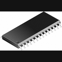
PIC14000-04I/SS Microchip Technology, PIC14000-04I/SS Datasheet - Page 86

PIC14000-04I/SS
Manufacturer Part Number
PIC14000-04I/SS
Description
IC, 8BIT MCU, PIC14, 4MHZ, SSOP-28
Manufacturer
Microchip Technology
Datasheet
1.PIC14000-04SO.pdf
(153 pages)
Specifications of PIC14000-04I/SS
Controller Family/series
PIC14
No. Of I/o's
22
Ram Memory Size
192Byte
Cpu Speed
4MHz
No. Of Timers
2
Interface
I2C
Digital Ic Case Style
SSOP
Core Size
8 Bit
Program Memory Size
4096 X 14
Embedded Interface Type
I2C
Rohs Compliant
Yes
Processor Series
PIC14000
Core
PIC
Data Bus Width
8 bit
Program Memory Type
EPROM
Data Ram Size
192 B
Interface Type
SPI, UART
Maximum Clock Frequency
20 MHz
Number Of Programmable I/os
22
Number Of Timers
1
Operating Supply Voltage
2.7 V to 6 V
Maximum Operating Temperature
+ 85 C
Mounting Style
SMD/SMT
Package / Case
SSOP-28
Development Tools By Supplier
ICE2000
Minimum Operating Temperature
- 40 C
On-chip Adc
14 bit
Lead Free Status / RoHS Status
Lead free / RoHS Compliant
- Current page: 86 of 153
- Download datasheet (767Kb)
PIC14000
10.7.1
The WDT has a nominal time-out period of 18 ms (with
no prescaler). The time-out periods vary with
temperature, V
specs). If longer time-out periods are desired, a pres-
caler with a division ratio of up to 1:128 can be
assigned to the WDT under software control by writing
to the OPTION registers. Thus, time-out periods up to
2.3 seconds can be realized. The CLRWDT and SLEEP
instructions clear the WDT and the prescaler, if
assigned to the WDT, and prevent it from timing out and
generating a device RESET.
The TO bit in the status register will be cleared upon a
watchdog timer time-out. The WDT time-out period (no
prescaler) is measured and stored in calibration space
at location 0FD2h.
TABLE 10-6:
DS40122B-page 86
CPU Clock
Main Oscillator
Watchdog Timer
Temperature Sensor
Low-voltage Detector
Comparator and
Programmable References
A/D Comparator
Programmable Current Source
Slope Reference Voltage Divider
Level Shift Networks
Bandgap Reference
Voltage Regulator Control
Power On Reset
Note:
WDT PERIOD
Refer to analog specs for individual peripheral operating currents.
DD
SUMMARY OF POWER MANAGEMENT OPTIONS
Function
and process variations (see DC
OFF during SLEEP/HIBERNATE mode, ON otherwise
ON if NOT in SLEEP mode. In SLEEP mode, controlled by OSCOFF
bit, SLPCON<3>.
Controlled by WDTE, 2007h<2> and HIBEN, SLPCON<7>
Controlled by TEMPOFF, SLPCON<1>
Controlled by REFOFF, SLPCON<5>
Controlled by CMOFF, SLPCON<2>
Controlled by ADOFF, SLPCON<0>
Controlled by ADOFF, SLPCON<0> and ADCON1<7:4>
Controlled by ADOFF, SLPCON<0>
Controlled by LSOFF, SLPCON<4>
Controlled by REFOFF, SLPCON<5>
Always ON. Does not consume power if unconnected.
Always ON, except in SLEEP/HIBERNATE mode
Preliminary
10.7.2
It should also be taken into account that under
worst-case conditions (minimum VDD, maximum
temperature, maximum WDT prescaler) it may take
several seconds before a WDT time-out occurs. Refer
to Section 6.3 for prescaler switching considerations.
10.8
The PIC14000 has several power management
options to prolong battery lifetime. The SLEEP instruc-
tion halts the CPU and can turn off the on-chip oscilla-
tors. The CPU can be in SLEEP mode, yet the A/D
converter can continue to run. Several bits are included
in the SLPCON register (8Fh) to control power to ana-
log modules.
WDT PROGRAMMING CONSIDERATIONS
Power Management Options
Summary
1996 Microchip Technology Inc.
Related parts for PIC14000-04I/SS
Image
Part Number
Description
Manufacturer
Datasheet
Request
R

Part Number:
Description:
IC MCU OTP 4KX14 A/D 28SOIC
Manufacturer:
Microchip Technology
Datasheet:

Part Number:
Description:
IC MCU OTP 4KX14 A/D 28SSOP
Manufacturer:
Microchip Technology
Datasheet:

Part Number:
Description:
IC MCU OTP 4KX14 A/D 28SOIC
Manufacturer:
Microchip Technology
Datasheet:

Part Number:
Description:
IC MCU OTP 4KX14 A/D 28DIP
Manufacturer:
Microchip Technology
Datasheet:

Part Number:
Description:
IC MCU OTP 4KX14 A/D 28SSOP
Manufacturer:
Microchip Technology
Datasheet:

Part Number:
Description:
IC MCU OTP 4KX14 A/D 28CDIP
Manufacturer:
Microchip Technology
Datasheet:

Part Number:
Description:
IC MCU OTP 4KX14 A/D 28DIP
Manufacturer:
Microchip Technology
Datasheet:

Part Number:
Description:
IC MCU OTP 4KX14 A/D 28SOIC
Manufacturer:
Microchip Technology
Datasheet:

Part Number:
Description:
IC MCU OTP 4KX14 A/D 28DIP
Manufacturer:
Microchip Technology
Datasheet:

Part Number:
Description:
IC MCU OTP 4KX14 A/D 28DIP
Manufacturer:
Microchip Technology
Datasheet:

Part Number:
Description:
IC MCU OTP 4KX14 A/D 28SOIC
Manufacturer:
Microchip Technology
Datasheet:

Part Number:
Description:
IC MCU OTP 4KX14 A/D 28SSOP
Manufacturer:
Microchip Technology
Datasheet:

Part Number:
Description:
28-Pin Programmable Mixed Signal Controller
Manufacturer:
Microchip Technology
Datasheet:


