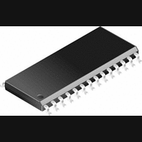
PIC14000-04I/SS Microchip Technology, PIC14000-04I/SS Datasheet - Page 83

PIC14000-04I/SS
Manufacturer Part Number
PIC14000-04I/SS
Description
IC, 8BIT MCU, PIC14, 4MHZ, SSOP-28
Manufacturer
Microchip Technology
Datasheet
1.PIC14000-04SO.pdf
(153 pages)
Specifications of PIC14000-04I/SS
Controller Family/series
PIC14
No. Of I/o's
22
Ram Memory Size
192Byte
Cpu Speed
4MHz
No. Of Timers
2
Interface
I2C
Digital Ic Case Style
SSOP
Core Size
8 Bit
Program Memory Size
4096 X 14
Embedded Interface Type
I2C
Rohs Compliant
Yes
Processor Series
PIC14000
Core
PIC
Data Bus Width
8 bit
Program Memory Type
EPROM
Data Ram Size
192 B
Interface Type
SPI, UART
Maximum Clock Frequency
20 MHz
Number Of Programmable I/os
22
Number Of Timers
1
Operating Supply Voltage
2.7 V to 6 V
Maximum Operating Temperature
+ 85 C
Mounting Style
SMD/SMT
Package / Case
SSOP-28
Development Tools By Supplier
ICE2000
Minimum Operating Temperature
- 40 C
On-chip Adc
14 bit
Lead Free Status / RoHS Status
Lead free / RoHS Compliant
- Current page: 83 of 153
- Download datasheet (767Kb)
10.6.1
An external interrupt can be generated via the
OSC1/PBTN pin if IN (internal oscillator) mode is
enabled. This interrupt is falling edge triggered. When
a valid edge appears on OSC1/PBTN pin, PBIF
(PIR1<4>) is set. This interrupt can be disabled by
clearing PBIE (PIE1<4>). PBIF must be cleared in soft-
FIGURE 10-10: EXTERNAL (OSC1/PBTN) INTERRUPT TIMING
1996 Microchip Technology Inc.
INSTRUCTION FLOW
INTERNAL
OSC
CLKOUT(3)
PBTN pin
PBIF flag
(PIR<4>)
GIE bit
(INTCON<7>)
PC
Instruction
fetched
Instruction
executed
EXTERNAL INTERRUPT
Notes:
1. PBIF flag is sampled here (every Q1)
2. Interrupt latency = 3-4Tcy where Tcy = instruction cycle time.
3. Available only in IN oscillator mode on OSC2.
4. For minimum width spec of PBTN pulse, refer to AC specs.
5. PBIF is enabled to be set anytime during the Q4-Q1 cycles.
Latency is the same whether Inst (PC) is a single cycle or a 2-cycle instruction.
Q1
Inst (PC-1)
Inst (PC)
1
Q2
PC
Q3 Q4
4
5
Q1
Inst (PC+1)
Inst (PC)
Q2
1
PC+1
Q3 Q4
Preliminary
Interrupt Latency
(Note 2)
Q1
Dummy Cycle
Q2
ware in the interrupt service routine before re-enabling
the interrupt. This interrupt can wake up the processor
from SLEEP if PBIE bit is set (interrupt enabled) prior
to going into SLEEP mode. The status of the GIE bit
determines whether or not the processor branches to
the interrupt vector following wake-up. The timing of the
external interrupt is shown in Figure 10-10.
PC+1
—
Q3 Q4
Q1
Dummy Cycle
Inst (0004h)
Q2
0004h
Q3 Q4
PIC14000
Q1
DS40122B-page 83
Inst (0005h)
Q2
Inst (0004h)
0005h
Q3 Q4
Related parts for PIC14000-04I/SS
Image
Part Number
Description
Manufacturer
Datasheet
Request
R

Part Number:
Description:
IC MCU OTP 4KX14 A/D 28SOIC
Manufacturer:
Microchip Technology
Datasheet:

Part Number:
Description:
IC MCU OTP 4KX14 A/D 28SSOP
Manufacturer:
Microchip Technology
Datasheet:

Part Number:
Description:
IC MCU OTP 4KX14 A/D 28SOIC
Manufacturer:
Microchip Technology
Datasheet:

Part Number:
Description:
IC MCU OTP 4KX14 A/D 28DIP
Manufacturer:
Microchip Technology
Datasheet:

Part Number:
Description:
IC MCU OTP 4KX14 A/D 28SSOP
Manufacturer:
Microchip Technology
Datasheet:

Part Number:
Description:
IC MCU OTP 4KX14 A/D 28CDIP
Manufacturer:
Microchip Technology
Datasheet:

Part Number:
Description:
IC MCU OTP 4KX14 A/D 28DIP
Manufacturer:
Microchip Technology
Datasheet:

Part Number:
Description:
IC MCU OTP 4KX14 A/D 28SOIC
Manufacturer:
Microchip Technology
Datasheet:

Part Number:
Description:
IC MCU OTP 4KX14 A/D 28DIP
Manufacturer:
Microchip Technology
Datasheet:

Part Number:
Description:
IC MCU OTP 4KX14 A/D 28DIP
Manufacturer:
Microchip Technology
Datasheet:

Part Number:
Description:
IC MCU OTP 4KX14 A/D 28SOIC
Manufacturer:
Microchip Technology
Datasheet:

Part Number:
Description:
IC MCU OTP 4KX14 A/D 28SSOP
Manufacturer:
Microchip Technology
Datasheet:

Part Number:
Description:
28-Pin Programmable Mixed Signal Controller
Manufacturer:
Microchip Technology
Datasheet:


