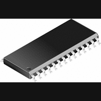
PIC14000-04I/SS Microchip Technology, PIC14000-04I/SS Datasheet - Page 25

PIC14000-04I/SS
Manufacturer Part Number
PIC14000-04I/SS
Description
IC, 8BIT MCU, PIC14, 4MHZ, SSOP-28
Manufacturer
Microchip Technology
Datasheet
1.PIC14000-04SO.pdf
(153 pages)
Specifications of PIC14000-04I/SS
Controller Family/series
PIC14
No. Of I/o's
22
Ram Memory Size
192Byte
Cpu Speed
4MHz
No. Of Timers
2
Interface
I2C
Digital Ic Case Style
SSOP
Core Size
8 Bit
Program Memory Size
4096 X 14
Embedded Interface Type
I2C
Rohs Compliant
Yes
Processor Series
PIC14000
Core
PIC
Data Bus Width
8 bit
Program Memory Type
EPROM
Data Ram Size
192 B
Interface Type
SPI, UART
Maximum Clock Frequency
20 MHz
Number Of Programmable I/os
22
Number Of Timers
1
Operating Supply Voltage
2.7 V to 6 V
Maximum Operating Temperature
+ 85 C
Mounting Style
SMD/SMT
Package / Case
SSOP-28
Development Tools By Supplier
ICE2000
Minimum Operating Temperature
- 40 C
On-chip Adc
14 bit
Lead Free Status / RoHS Status
Lead free / RoHS Compliant
- Current page: 25 of 153
- Download datasheet (767Kb)
5.0
The PIC14000 has three ports, PORTA, PORTC and
PORTD, described in the following paragraphs.
Generally, PORTA is used as the analog input port.
PORTC is used for general purpose I/O and for host
communication. PORTD provides additional I/O lines.
Four lines of PORTD may function as analog inputs.
5.1
PORTA is a 4-bit wide port with data register located at
location 05h and corresponding data direction register
(TRISA) at 85h. PORTA can operate as either
analog inputs for the internal A/D converter or as
general purpose digital I/O ports. These inputs are
Schmitt Triggers when used as digital inputs, and have
CMOS drivers as outputs.
PORTA pins are multiplexed with analog inputs.
ADCON1<1:0> bits control whether these pins are
analog or digital as shown in Section 8.7. When config-
ured to the digital mode, reading the PORTA register
reads the status of the pins whereas writing to it will
write to the port latch. When selected as an analog
input, these pins will read as ‘0’s.
FIGURE 5-1:
1996 Microchip Technology Inc.
I/O PORTS
PORTA and TRISA
PORTA BLOCK DIAGRAM
TRISA
Write
Read
PORTA
Write
PORTA
Data
Bus
This document was created with FrameMaker 4 0 4
To A/D Converter
Note: I/O pins have protection diodes to V
D
CK Q
D
CK Q
Read
TRISA
Q
Q
Preliminary
Analog Input Mode
Q
Schmitt Trigger
EN
Input Buffer
D
The TRISA register controls the direction of the PORTA
pins, even when they are being used as analog inputs.
The user must make sure to keep the pins configured
as inputs when using them as analog inputs. A ‘1’ in
each location configures the corresponding port pin as
an input. This register resets to all ‘1’s, meaning all
PORTA pins are initially inputs. The data register
should be initialized prior to configuring the port as out-
puts. See Figure 5-2 and Figure 5-3.
PORTA inputs go through a Schmitt Trigger AND gate
that is disabled when the input is in analog mode. Refer
to Figure 5-1.
Note that bits RA<7:4> are unimplemented and always
read as ‘0’. Unused inputs should not be left floating to
avoid leakage currents. All pins have input protection
diodes to V
EXAMPLE 5-1:
CLRF
BSF
MOVLW 0x0F
MOVWF TRISA
V
Note:
SS
V
N
P
DD
PORTA
STATUS, RP0 ;Select Bank1
On Reset, PORTA is configured as analog
inputs
DD
DD
I/O
Pin
and V
and V
SS
INITIALIZING PORTA
SS
;Initialize PORTA by setting
;output data latches
;Value used to initialize
;data direction
;Set RA<3:0> as inputs
.
.
PIC14000
DS40122B-page 25
Related parts for PIC14000-04I/SS
Image
Part Number
Description
Manufacturer
Datasheet
Request
R

Part Number:
Description:
IC MCU OTP 4KX14 A/D 28SOIC
Manufacturer:
Microchip Technology
Datasheet:

Part Number:
Description:
IC MCU OTP 4KX14 A/D 28SSOP
Manufacturer:
Microchip Technology
Datasheet:

Part Number:
Description:
IC MCU OTP 4KX14 A/D 28SOIC
Manufacturer:
Microchip Technology
Datasheet:

Part Number:
Description:
IC MCU OTP 4KX14 A/D 28DIP
Manufacturer:
Microchip Technology
Datasheet:

Part Number:
Description:
IC MCU OTP 4KX14 A/D 28SSOP
Manufacturer:
Microchip Technology
Datasheet:

Part Number:
Description:
IC MCU OTP 4KX14 A/D 28CDIP
Manufacturer:
Microchip Technology
Datasheet:

Part Number:
Description:
IC MCU OTP 4KX14 A/D 28DIP
Manufacturer:
Microchip Technology
Datasheet:

Part Number:
Description:
IC MCU OTP 4KX14 A/D 28SOIC
Manufacturer:
Microchip Technology
Datasheet:

Part Number:
Description:
IC MCU OTP 4KX14 A/D 28DIP
Manufacturer:
Microchip Technology
Datasheet:

Part Number:
Description:
IC MCU OTP 4KX14 A/D 28DIP
Manufacturer:
Microchip Technology
Datasheet:

Part Number:
Description:
IC MCU OTP 4KX14 A/D 28SOIC
Manufacturer:
Microchip Technology
Datasheet:

Part Number:
Description:
IC MCU OTP 4KX14 A/D 28SSOP
Manufacturer:
Microchip Technology
Datasheet:

Part Number:
Description:
28-Pin Programmable Mixed Signal Controller
Manufacturer:
Microchip Technology
Datasheet:


